E5EX–H
E5EX–H
12
Level 2
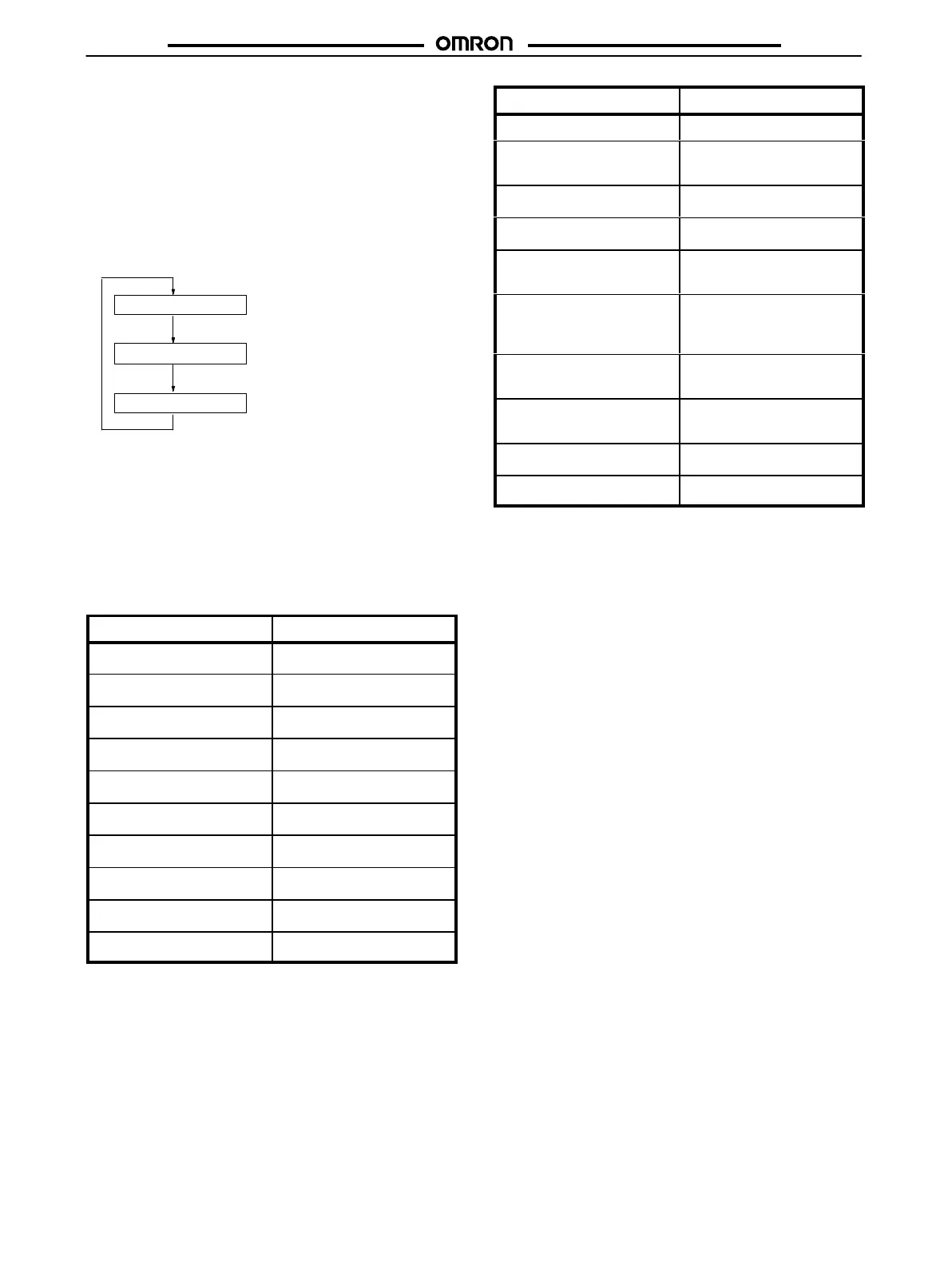
In level 2 the control output variable, temperature sensor, and
modes
for alarm output can
be monitored. Note that level 2 is a mon
-
itoring
level only and thus no parameter can be changed. When the
level
key is pressed for more than 2 seconds after power up,
5l-l is
displayed on the PV display. After this message has been dis-
played, holding down the Level key again for 2 seconds or more
causes
o
to be displayed on the PV display
. When this message has
been displayed, the control output variable, selected temperature
sensor, and alarm modes can be monitored each time the display
key is pressed, as follows:
Press a.
Press a.
Press a.
T
emperature sensor
Control output variable
Alarm mode
o
in-t
al
Control Output V
ariable:
o
When
the T
emperature Controller enters level 2, the control output
amount
is displayed on the SV display in a
range of 0.0% to 100.0%.
Temperature
Sensor:
in-t
When in-t is displayed on the PV display, a message identifying
the
selected temperature sensor
, i.e., the present setting of the tem
-
perature
sensor selector (SW206), is displayed on the SV display
.
The following table shows the messages that may be displayed:
Display Sensor
r pr
R
5 pr
S
k ca
K
j ic
J
t cc
T
e cr
E
jpt
JPt100*
pt
Pt100**
l ic
L
u cc
U
*Meets
JIS 1981.
**Meets JIS 1989, DIN.
AL (Alarm Mode):
al
While
al
is displayed on the PV display in level 2,
a message identi
-
fying
the mode for alarm output or the present setting of the corre
-
sponding
alarm mode selector
(SW205) is displayed on the SV dis
-
play.
The following table shows the possible messages that may ap
-
pear
on the SV display
.
Display
Alarm mode
No display No alarm
)--(
Upper- and lower-limit
alarms
---(
Upper-limit alarm
)---
Lower-limit alarm
-()-
Inverse upper- and lower-
limit alarm
3--e
Upper- and lower-limit
alarms with standby se-
quence
---e
Upper-limit alarm with
standby sequence
3---
Lower-limit alarm with
standby sequence
1--c
Event alarm
pro
Proportional alarm

 Loading...