E5EX–H
E5EX–H
5
Operation
NOTICE: Always turn of
f the power supply to the T
emperature Controller before changing any switch settings.
Accessing Switches and Selectors
Before
supplying power to the T
emperature Controller
, the selectors and switches shown below must be set to specify the temperature sensor
,
functions,
and alarm mode. The T
emperature Controller must be equipped with one of the six
Control Output Units. The Control Output Unit
must
be ordered separately
.
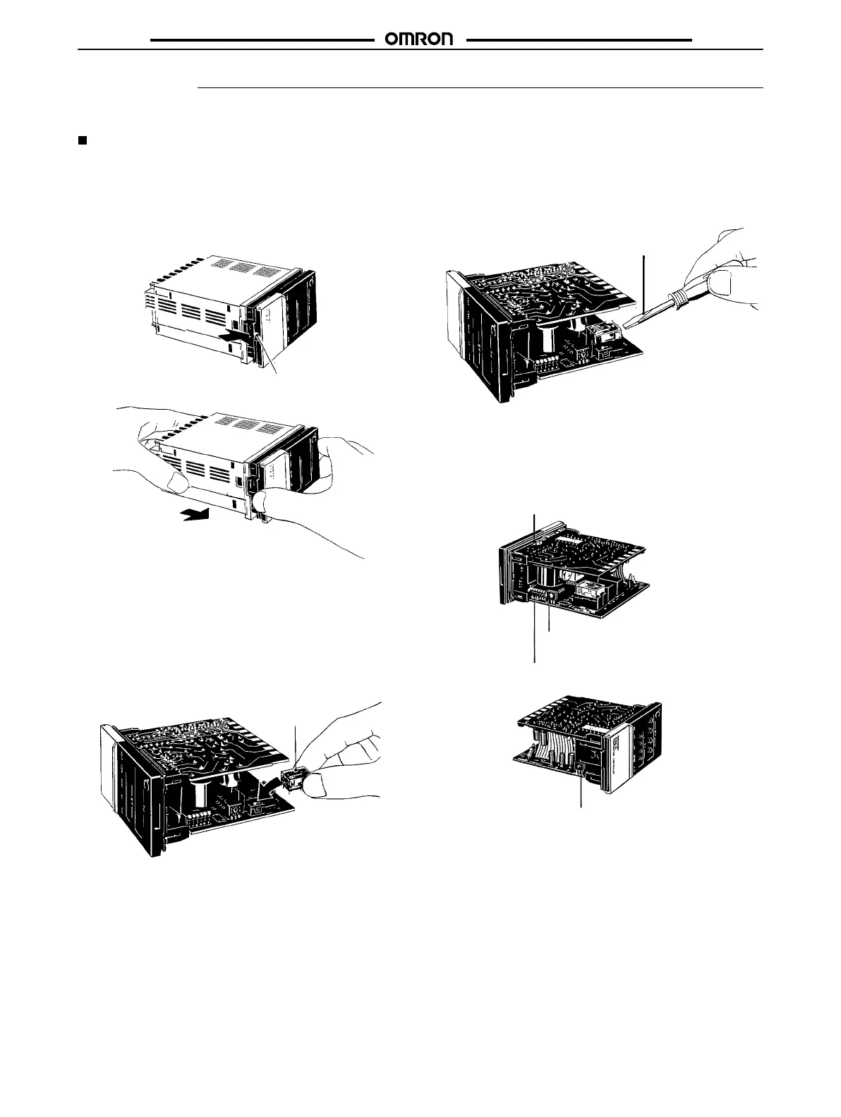
1.
Remove the internal mechanism from the housing. Lift the
internal
mechanism while pressing the hook at the bottom of
the
front panel.
Hook
Pull out the internal mechanism while holding
down the hook with your finger
.
2.
Connect
a Control Output Unit to the vacant socket
on one of
the printed circuit boards (see the figure below). A white
square
is marked
on the Control Output Unit. Be sure to install
the
Unit with this
marking facing the direction indicated by the
arrow
in the figure below
.
Mount the Control Output Unit
with this mark facing the di
-
rection indicated by the arrow
.
T
o remove a Control Output Unit, push it up with the tip of a
flat-bladed screwdriver as illustrated below
.
Flat-blade
screwdriver
3.
Three
internal switches must be set: the temperature sensor
selector, the operating mode selector, and the alarm mode
selector.
The following figure shows the locations of internal
switches on the internal mechanism.
Alarm mode selector (SW205)
Protection switch (SW101)
Operating mode selector (SW201)
T
emperature sensor
selector (SW206)

 Loading...