E5EX–H
E5EX–H
15
Precautions
Mounting
The dimensions of the Temperature Controller conform to DIN
43700.
Recommended panel thickness is 1 to 8 mm.
Do not install the Temperature Controller in a location exposed to
excessive
dust or corrosive gases. Moreover
, avoid locations sub
-
ject
to heavy vibration
or shock, water or oil spray
, or high tempera
-
tures.
Isolate the T
emperature
Controller from equipment that gen
-
erates
strong, high-frequency
noises such as high-frequency weld
-
ers.
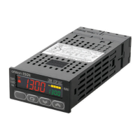
Attach
the two mounting fixtures supplied with E5EX–AH on the top
and
bottom
of the T
emperature Controller
. T
ighten the screws of the
mounting
fixtures with your fingers.
Connection Examples
With
Solderless T
erminal:
Use M3.5 solderless terminals with the Temperature Controller’s
M3.5 self-rising pressure plate screws.
Solder-dipped Leads:
Strip
6 to 12 mm of
the lead wires and carefully arrange the wire tips.
Do
not tighten the
terminal screw with excessive force. The terminal
block
of the T
emperature Controller is
constructed so that the lead
wires
can be connected to all the
terminals from the same direction.
Top
Bottom
Temperature Sensor Connection
To
reduce induced
noise, the lead wires connecting the temperature
sensor
to the T
emperature Controller must be separated from pow
-
er
lines and load lines.
Use the specified compensating conductors for thermocouples.
When
using a thermocouple as the temperature
sensor
, attach the
short-circuit bar shown in the terminal block diagram
on the hous
-
ing.
Use lead wires having a small resistance for temperature
resis
-
tance
thermometers.
Be sure to remove the short-circuit bar from the terminals when a
temperature
resistance thermometer is used.
Sequenced Circuits
Several
seconds are
required until the relay is turned ON after pow
-
er
has been supplied to the T
emperature Controller
. Therefore, take
this time delay into consideration when designing sequenced cir-
cuits
which incorporate a T
emperature Controller
.
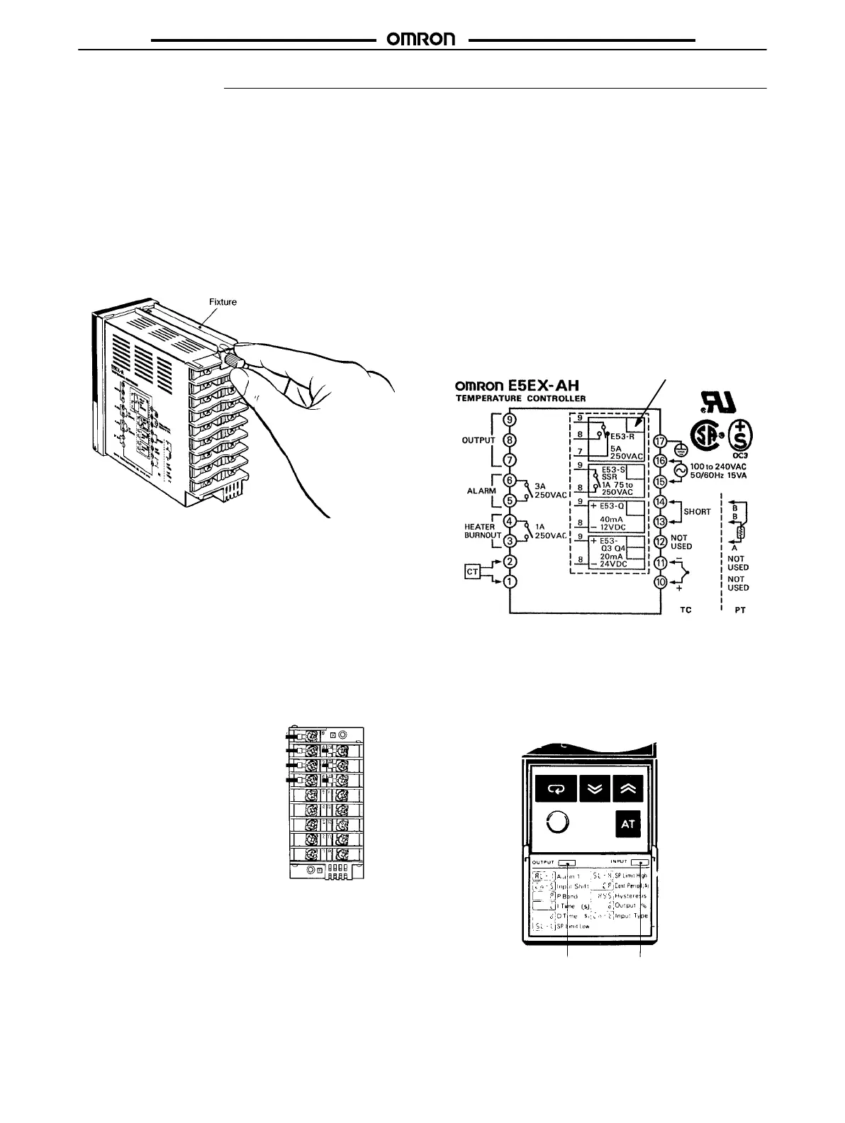
Terminal Layout Diagram on the Housing
The
T
emperature Controller allows an input and output device to be
freely selected. Use the terminal layout diagram attached on the
housing
of the T
emperature Controller to identify the output
device
mounted
in the
T
emperature Controller
, by making the diagram as
follows:
Check here with a felt-tip pen.
Stickers
Stickers
indicating the
temperature sensor type (R, S, K, J, etc.) and
Control
Output Unit (R, S,
and Q) are supplied with the T
emperature
Controller.
Attach these stickers on the front panel as shown,
allow
-
ing
the temperature sensor and Control
Output Unit mounted in the
Temperature
Controller can be easily discerned.
Sticker identifying
Control Output Unit
Sticker identifying
temperature sensor

 Loading...