H3DEH3DE
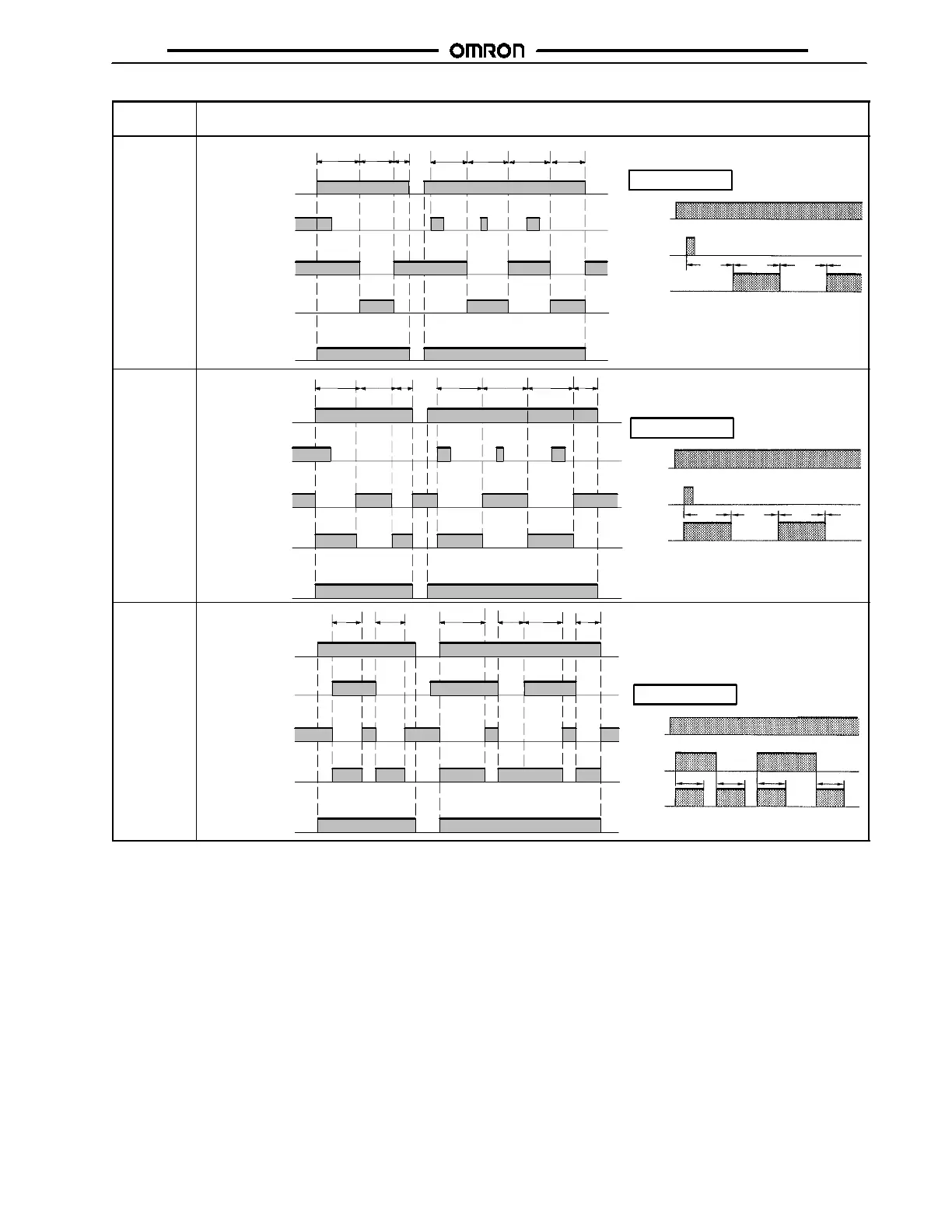
Timing Chart —
continued from previous page
Operating
mode
Timing chart
B:
Repeat-
cycle OFF
start
Basic operation
Power
Start
Output
t t t t
t tt--a t t t t--a
Power (A
1
and A
2
)
Start (B
1
and A
2
)
(See Note.)
Power indicator
* For power-on operation, impos e voltage to the
Start input. The Timer starts operating at the
moment the power is turned on.
** Start input is invalid while the Timer is in opera-
tion.
Output relay: NC
15 and 16
(25 and 26)
Output relay: NO
(output indicator)
15 and 18
(25 and 28)
*
**
B2:
Repeat-
cycle ON
start
Basic operation
Power
Start
Output
t t t t
Power (A
1
and A
2
)
Start (B
1
and A
2
)
(See Note.)
Power indicator
ttt t -- a t t t -- a
* For power-on operation, impose v oltage to the
Start input. The Timer starts operating at the
moment the power is turned on.
** Start input is invalid while the Timer is in opera-
tion.
Output relay: NC
15 and 16
(25 and 26)
Output relay: NO
(output indicator)
15 and 18
(25 and 28)
*
**
C:
Signal
ON/OFF-
delay
Basic operation
Power
Start
Output
tt
t
t
Power (A
1
and A
2
)
Start (B
1
and A
2
)
(See Note.)
Power indicator
tt
t t t-- a t-- a
* Start input is invalid while the Timer is in opera-
tion.
Output relay: NC
15 and 16
(25 and 26)
Output relay: NO
(output indicator)
15 and 18
(25 and 28)
*
Note: The start input of the H3DE-M1 or H3DE-M2 model is activated by applying a voltage to B1 and A2 terminals.
The voltage can be applied by turning on the contact between B1 and A1 (Refer to Terminal Arrangement).
(This table continues on the next page.)
 Loading...