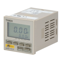
H5F
H5F
232
Characteristics
Accuracy of operating time
!
0.01%
!
0.05 s max. (see note 1)
Setting error
Influence of voltage
Influence of temperature
Cyclic error Monthly difference
!
15 s (at 25
"
C)
Memory protection 5 years min. (at 25
"
C) (see note 2)
Insulation resistance 100 M
$
min. (between terminals and non-current-carrying metal parts, between operating
circuit and contact output circuit and between non-continuous contacts)
Dielectric strength 2,000 VAC, 50/60 Hz for 1 min (between terminals and non-current-carrying metal parts and
between operating circuit and contact output circuit)
1,000 VAC, 50/60 Hz for 1 min (between non-continuous contacts)
Noise immunity 1.5 kV (square wave noise having 100 ns width, 1 ns rise time,
!
polarity and 0
"
to 360
"
phase
is applied by noise simulator
Vibration resistance Destruction: 10 to 55 Hz with 0.75-mm double amplitude
Malfunction: 10 to 55 Hz with 0.5-mm double amplitude
Shock resistance Destruction: 300 m/s
2
(approx. 300G)
Malfunction: 100 m/s
2
(approx. 10G)
Ambient temperature Operating: --10
"
Cto55
"
C (with no icing)
Ambient humidity Operating: 35% to 85%
Life expectancy Mechanical: 50,000 operations min. (15 A, 250 VAC, resistive load)
50,000 operations min. (1 HP, 250 VAC, motor load)
50,000 operations min. (10 A, 250 VAC, inductive load (cos
%
=0.7))
50,000 operations min. (100 W, 100 VAC, lamp load)
10,000 operations min. (300 W, 100 VAC, lamp load)
Approved standards UL (File No. E41515), CSA (File No. LR22310)
Weight H5F-B: approx. 115 g; H5F-KB: approx. 160 g; H5F-FB: approx. 130 g
Note: 1. The total error including the repeat accuracy, setting error, variation due to voltage change, and variation due to temperature
change is
!
0.01%
!
0.05 s max.
!
0.01% also indicates an error in the time interval of a set time.
2. The total time when power is not being supplied.
Operation
Operation method Digital quartz
Operation 1. Daily operation (Multiple-day operation possible)
2. Pulse-output operation (pulse width can be set in units of 1 s from 1 to 59 s and in units of
1minfrom1to60min)
3. Partial operation on specified day (one or some of operations for certain days can also be
executed on other days.)
4. Forced ON/OFF operation
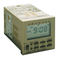
Display 1. Day, hours (a.m., p.m.), minutes (0:00 to 11:59 a.m., 0:00 to 11:59 p.m.)
2. Digital display by LCD. Character height: 8 mm
3. Digital display of present time and time schedules for operation
4. Timing chart display of present time and time schedules for operation
Number of circuits 1 independent circuit
Setting method Key switch
Minimum setting unit 1min
Minimum set interval 1min
Number of operations that can be
set
16 (see note)
Note: Up to 8 ON/OFF operations are possible per day. (For pulse operation, the number is 16.)
Operation Function
Timer operation Controls the output according to preset of ON and OFF times (the time can be set in units of
1min)
Pulse-output Produces output for a fixed duration at the preset ON time (pulse width: 1 to 59 s, or 1 to 59
min). The pulse width can be set in units of 1 s or 1 min.
Forced ON/OFF operation Forcibly turns ON/OFF the output by a slide switch
Partial operation on specified day Part of one day’s operation programmed for any weekday from Sunday to Saturday can be
executed. (Convenient, for example, for executing a half-day operation on Saturday.)
Note: Both the timer operation and the pulse operation cannot be programmed together with.
 Loading...