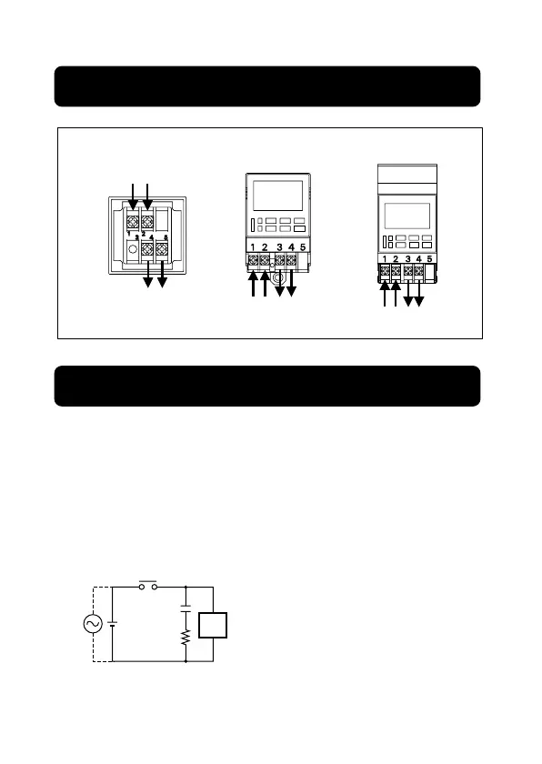
●H5F-B
(Rear View)
●H5F-FB
(Front View)
●H5F-KB
(Front View)
- 31 -
Read the following information before performing wiring.
●The Time Switch output is no-voltage contact output.A power supply
must be provided to drive the load. Perform wiring according to the
information on the next page.
●When driving an inductive load (e.g., coil), a surge voltage is generated
when the contacts (i.e., Time Switch output) are switched, and in some
cases this may damage other devices connected to the Time Switch or
the same line. Absorb the surge with a capacitor and resistor as shown
in the following diagram.
Time Switch output
As a rough guide, the capacitor (C) and resistor (R)
should have the following specifications:
C: 0.5 to 1 µF for a switching current of 1 A
R: 0.5 to 1 Ω for a switching voltage of 1 V
• Use a capacitor with a dielectric strength
appropriate for the power supply voltage.
Use an AC-type capacitor with AC circuits.
There may be cases where, due to inconsistencies
in the nature and characteristics of the load, delays
in restoring the load may cause problems. Be sure
to confirm that correct operation is possible under
the actual operating conditions.
Power supply
Output
Power
supply
Output
Power
supply
Output
• Power supply and output are not
connected internally.
• Terminal screw size : M3.5
2. Connections
3. Wiring
inductive
load
Power
supply
C
R
 Loading...