9
H8CA-SH8CA-S
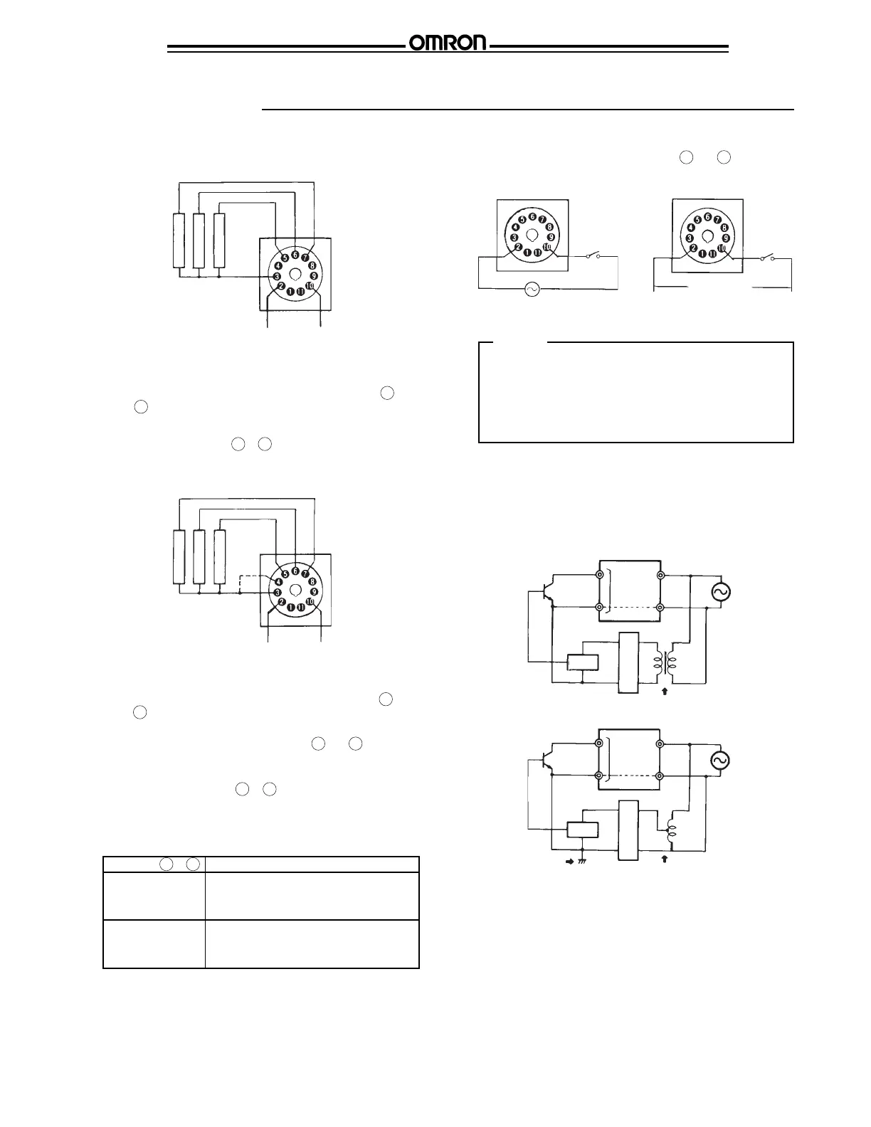
Connections
Reset input
Power
Supply
Reset input
Start input
Gate input
Power
Supply
Count input 1
Count input 2
■ POWER SUPPLY CONNECTION
Connect power supply across terminals 2 and 10 and apply
one of the specified voltages. (Pay special attention to the
polarity when using a DC-operated model.)
Cautions
Do not touch the input terminals while power is supplied to
the H8CA-S; otherwise, you will feel electric shock,
because the counter does not have any power transformer
built in. Use of a model rated at a low DC voltage is
recommended when the counter is to be installed at a
location where the input terminals are easily accessible.
Notice:
When connecting external signal input contacts and transis-
tors, use a power supply having a power transformer whose
primary and secondary circuits are isolated from each other
with the secondary circuit not grounded, for the input devices,
to prevent current feedback and short-circuiting.
H8CA-S
Input
terminals
Circuit
Power supply
Insulated transformer is
necessary
Rectifier
Input
terminals
H8CA-S
Power supply
Circuit
Autotransformer
Grounding
Rectifier
Correct:
Incorrect:
Notice:
Do not arrange the peripheral circuits of the counter in either
way, as the internal circuit may be destroyed, rendering the
counter unoperational.
To input a signal from a single input contact to several
H8CA-Ss at the same time, be sure to connect the terminals of
the same numbers in parallel.
■ TERMINAL ARRANGEMENTS
In counter function mode
Note: When the control power supply is DC, terminals 2 and
3 are internally connected.
Mode switch terminals ( 1 & 3 )
When these terminals are short-circuited, set the input and
output modes with the RESET key, not the MODE key.
In timer function mode
Note: When the control power supply is DC, terminals 2 and
3 are internally connected.
* Check the operating status of terminals 3 and 4 (see
table below) before connecting or disconnecting them.
Timer control terminals ( 3 & 4 )
Be sure these terminals are not connected when using
H8CA-S as a counter. These terminals are used as shown
below only when H8CA-S functions as a timer.
Open
24 to 240 VAC (50/60 Hz)
12 to 120 VDC
(-) (+)
Short-circuited
Terminals 3 & 4
Operation
Timer operation temporarily interrupted
when power failure accures in control
power supply
Timer operation continues even when
power failure accurs in control power
supply
 Loading...