MX2 7
Standard connections
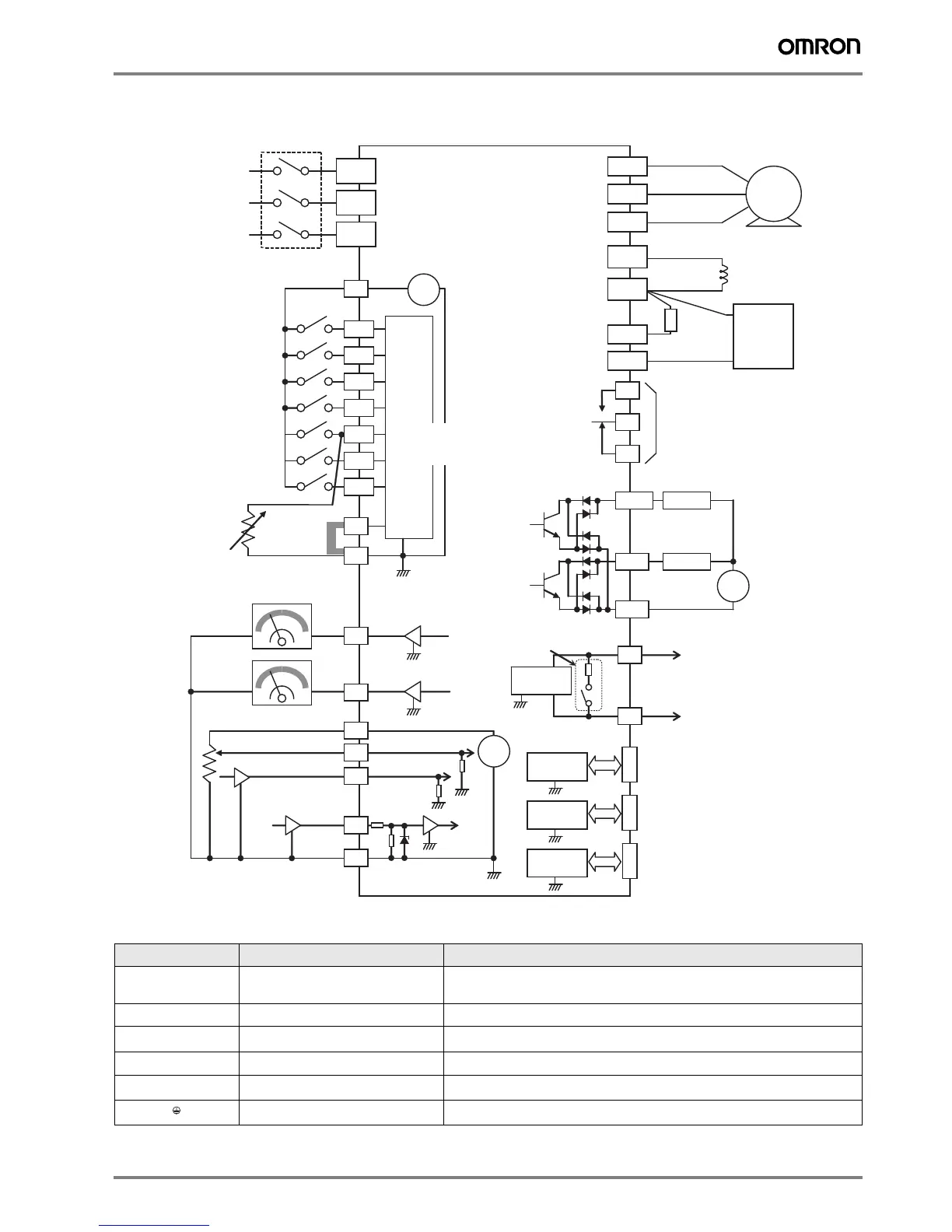
Terminal Block Specifications
Terminal Name Function (signal level)
R/L1, S/L2, T/L3
Main circuit power supply input Used to connect line power to the drive.
Drives with single-phase 200 V input power use only terminals R/L1 and N (T/L3), terminal
S/L2 is not available for these units
U/T1, V/T2, W/T3
Inverter output Used to connect the motor
PD/+1, P/+
External DC reactor terminal Normally connected by the short-circuit bar. Remove the short-circuit bar between +1 and P/
+2 when a DC reactor is connected.
P/+, N/-
Regenerative braking unit terminal
Connect optional regenerative braking units (If a braking torque is required)
P/+, RB
Braking resistor terminals
Connect option braking resistor (if a braking torque is required)
Grounding For grounding (grounding should conform to the local grounding code.)
Input
circuits
24V
P24
+ -
1
2
3/GS1
4/GS2
5/PTC
Forward
Thermistor
GND for logic inputs
AM
Meter
H
L
Analog reference
0~10VDC
4~20mA
GND for analog signals
MX2
Motor
PD/+1
P/+
R
(L1)
S
(L2)
T
N(L3)
U
(T1)
V
(T2)
W
(T3)
N/-
AL1
AL0
AL2
6
7/EB
EO
Meter
RB
11/EDM
Load
Freq. arrival signal
Open collector output
Output circuit
GND for logic outputs
12
Load
+
-
CM2
L
L
+
-
O
OI
EA
Apprx.10kΩ
10Vdc
Apprx.100Ω
L
L
Option port connector
L
L
L
L
L
L
SP
SN
)
L
PLC
Short bar
(Source type)
Breaker, MCCB
or GFI
Power source,
3-phase or
1-phase, per
inverter model
Intelligent inputs,
7 terminals
NOTE: For the wiring
of intelligent I/O and
analog inputs, be sure
to use twisted pair/
shielded cable. Attach
the shielded wire for
each signal to its
respective common
terminal at the inverter
end only.
Input impedance of
each intelligent input is
4.7kΩ
[5] configurable as
discrete input or
thermistor input
Pulse train input
24Vdc 32kHz max.
RS485
transceiver
USB
transceiver
Option port
controller
USB (mini-B) port
(PC communication port)
USB power: Self power
RJ45 port
(Optional operator port)
RS485
transceiver
Serial communication port
(RS485/ModBus)
Termination resistor (200Ω)
(Change by slide switch)
Relay contacts,
type 1 Form C
Brake
resistor
(optional)
Braking
unit
(optional)
DC reactor
(optional)
 Loading...


