8 Frequency inverters
Control Circuit
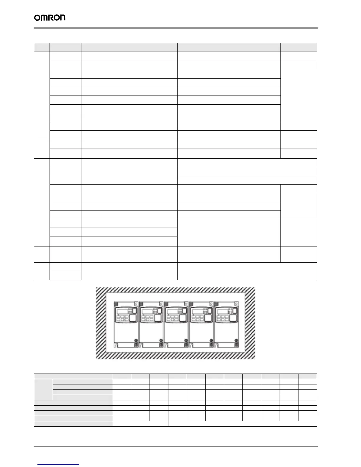
Side by side mounting
Inverter heat loss
Three-phase 200 V class
Type No.
Signal name Function Signal level
Digital input signals
PLC
Intelligent input common
Source type: connecting [P24] to [1]-[7] turns inputs ON
Sink type: connecting [L] to [1]-[7] turns inputs ON
-
P24
Internal 24 VDC 24 VDC, 30mA 24 VDC, 30 mA
1
Multi-function Input selection 1 Factory setting: Forward/ Stop
27 VDC max
2
Multi-function Input selection 2 Factory setting: Reverse/ Stop
3/ST1
Multi-function Input selection 3 / safe stop input 1 Factory setting: External trip
4/ST2
Multi-function Input selection 4 / safe stop input 2 Factory setting: Reset
5/PTC
Multi-function Input selection 5 / PTC thermistor input Factory setting: Multi-step speed reference 1
6
Multi-function input selection 6 Factory setting: Multi-step speed reference 2
7/EB
Multi-function input selection 7 / Pulse train input B Factory setting: Jog
L
Multi-function Input selection common (in upper row) -- --
Pulse
train
EA
Pulse train input A Factory setting: Speed reference
32 kHz max
5 to 24 VDC
EO
Pulse train output LAD frequency
10 VDC 2 mA
32 kHz max
Analog input
signal
H
Frequency reference power supply 10 VDC 10 mA max
O
Voltage frequency reference signal 0 to 10 VDC (10 kΩ)
OI
Current frequency reference signal 4 to 20 mA (250 Ω)
L
Frequency reference common (bottom row) --
Digital output
signals
11/EDM
Discrete logic output 1 / EDM output
Factory setting: During Run
27 VDC, 50 mA max
EDM based on
ISO13849-1
12
Discrete logic output 2 Factory setting: Frequency arrival type 1
CMD
GND logic output --
AL0
Relay commom contact
Factory setting: Alarm signal
Under normal operation
AL1 - AL0 Closed
AL2 - AL0 Open
R load
250 VAC 2.5 A
30 VDC 3.0 A
I load
250 VAC 0.2 A
30 VDC 0.7 A
AL1
Relay contact, normally open
AL2
Relay contact, normally closed
Monitor
Signal
AM
Analog voltage output Factory setting: LAD frequency 0 to 10 VDC 1 mA
Comms
SP
Serial communication terminal RS485 Modbus communication
SN
Model MX2 A2001 A2002 A2004 A2007 A2015 A2022 A2037 A2055 A2075 A2110 A2150
Inverter
capacity
kVA
200 VT
0.4 0.6 1.2 2.0 3.3 4.1 6.7 10.3 13.8 19.3 23.9
200 CT
0.2 0.5 1.0 1.7 2.7 3.8 6.0 8.6 11.4 16.2 20.7
240 VT
0.4 0.7 1.4 2.4 3.9 4.9 8.1 12.4 16.6 23.2 28.6
240 CT
0.3 0.6 1.2 2.0 3.3 4.5 7.2 10.3 13.7 19.5 24.9
Rated current (A) VT
1.2 1.9 3.4 6.0 9.6 12.0 19.6 30.0 40.0 56.0 69.0
Rated current (A) CT
1.0 1.6 3.0 5.0 8.0 11.0 17.5 25.0 33.0 47.0 60.0
Total heat loss
12 22 30 48 79 104 154 229 313 458 625
Efficiency at rated load
89.5 90 93 94 95 95.5 96 96 96 96 96
Cooling Method Self cooling
Forced-air-cooling
 Loading...


