5-17
5 Modbus Connection
NB-series Programmable Terminals Host Connection Manual (V108)
5-9 Example of E5CC/E5EC, 3G3MX2 connection using Modbus RTU Extend
Protocol
5
Precautions for Correct Use
Precautions for Correct Use
• An address is written in hexadecimal in E5
C Digital Temperature Controllers
COMMUNICATION MANUAL (Cat. No. H175) or SYSDRIVE MX2 Series Multi-function
Compact Inverter USER’S MANUAL (Cat. No. I570) but needs to be input in decimal in NB-
Designer.
• Also, the top address starts with 0 in E5
C Digital Temperature Controllers
COMMUNICATION MANUAL (Cat. No. H175) or SYSDRIVE MX2 Series Multi-function
Compact Inverter USER’S MANUAL (Cat. No. I570) but needs to be changed by converting it
from hexadecimal to decimal and adding one for input in NB-Designer. An address has to start
with 1 in NB-Designer.
• When connecting to E5CC/E5EC, 2 byte mode address appoint method should be used.
Moreover, Use the addresses 2406 - 2407 for the status address with data length of 32 bit.
Data cannot be handled properly when the address 2001 is used.
• 3G3MX2 cannot access parameters with double word.
• 3G3MX2-V1 can access only low-order word of parameters with double word by using
Modbus mapping function. For details, please refer to SYSDRIVE MX2 Series Multi-function
Compact Inverter USER'S MANUAL (Cat. No. I570).
• When connecting to E5CC/E5EC or 3G3MX2, more than 1 of Unit No. should be used.
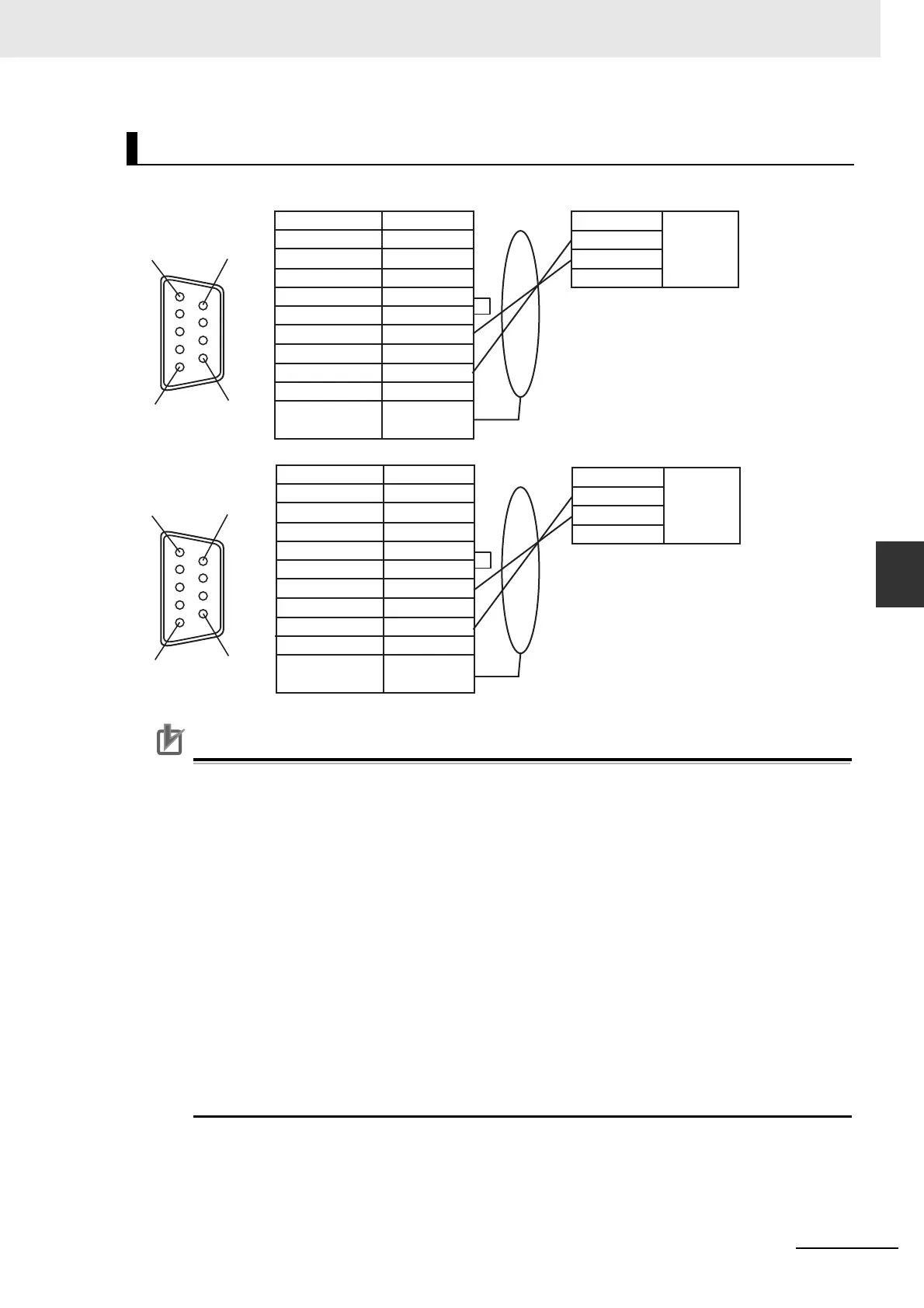
Cable Fabrication
16
95
16
95
NB7W-TW01B
COM2(female)
NB7W-TW01B
COM2(female)
Signal
SDB
+
SD(TXD)
RD(RXD)
Terminal 1
Terminal 2
RDB
+
SDA-
RDA-
SG
FG
Pin No.
1
2
3
4
5
6
7
8
9
Connector
shell
Signal
SDB
+
SD(TXD)
RD(RXD)
Terminal 1
Terminal 2
RDB
+
SDA-
RDA-
SG
FG
Pin No.
1
2
3
4
5
6
7
8
9
Connector
shell
E5CC/E5EC
RS-485
connector
Signal
A(
-)
B(+)
SG
3G3MX2
RS-485
connector
Signal
RS-
RS+
SG
 Loading...