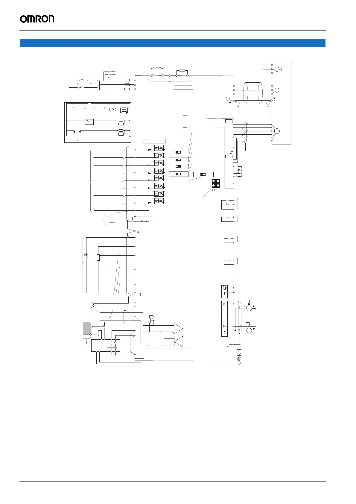
*1. When you install a DC reactor, you must remove the jumper between terminals +1 and +2.
*2. Models 4060 to 4675 have a DC reactor.
*3. Connect peripheral options to terminals -, +1, +2, B1 and B2.
*4. Use only SOURCE Mode for Safe Disable input.
*5. Disconnect the wire jumper between H1 and HC, and H2 and HC to use the Safe Disable input.
Q2A
Main circuit
Braking resistor
(option)
U
X
Short bar
DC reactor (option)
*1
*3
+2 +1 B1 B2-
Option card connector
CN5-C
CN5-B
CN5-A
U/T1
V/T2
W/T3
R/L1
S/L2
T/L3
Control circuit
DI1
DI2
DI3
DI4
DI5
DI6
DI7
DI8
D0V
DIC
D24V
+24 VDC
GND
Shield ground terminal
PI Pulse train input
(max. 32 kHz)
+10V
Power supply 10.5 VDC
(max. 20 mA)
AI1 Analog input 1(Frequency reference)
-10 to +10 VDC (20 k) / 0 to 10 VDC (20 k)
0 to 20 mA (250 ) / 4 to 20 mA (250 )
AI2 Analog input 2 (Frequency reference bias)
-10 to +10 VDC (20 k) / 0 to 10 VDC (20 k)
0 to 20 mA (250 ) / 4 to 20 mA (250 )
AI3 Analog input 3/PTC input
(Auxiliary frequency reference)
-10 to +10 VDC (20 k) / 0 to 10 VDC (20 k)
0 to 20 mA (250 ) / 4 to 20 mA (250 )
A0V
-10V
E24V
RS485+
RS485-
A0V
H1
H2
HC
D0V
Power supply, -10.5 VDC, max. 20 mA
Power supply input 24 VDC
Termination resistor
(120 , 1/2 W)
DIP switch S2
PG-B3
TB1
A+
A-
B+
B-
Z+
Z-
SD
FE
TB2
IP
IG
AO
IG
BO
IG
ZO
IG
1NO
1NC
1CM
2NO
2CM
3NO
3CM
4NO
4CM
PO
A0V
0 V
0 V
0 V
0 V
GND
AO1
AO2
AOV
DIP switch S2
Termination resistor ON/OFF
Jumper switch S5
Analog monitor voltage/
current (V)
DIP switch S4
AI3 analog input/
PTC input (AI)
DIP switch S1-3
AI3 voltage/
current (V)
DIP switch S1-2
AI2 voltage/
current (I)
DIP switch S1-1
AI1 voltage/
current (V)
V
I
FM
AM
V
I
V
I
V
I
AI PTC
OFF
ON
FU
FV
FW
Cooling
fan
M
r1
s1
t1
U
V
W
M
Shielded wire
PG
Monitor signal (phase A)
B pulse monitor signal
Fault relay output:
250 VAC, max. 1 A
30 VDC, max. 1 A
(min. 5 VDC, 10 mA)
MFDO (During Run):
250 VAC, max. 1 A
30 VDC, max. 1 A
(min. 5 VDC, 10 mA)
MFDO (Zero Speed):
250 VAC, max. 1 A
30 VDC, max. 1 A
(min. 5 VDC, 10 mA)
MFDO (Speed Agree 1):
250 VAC, max. 1 A
30 VDC, max. 1 A
(min. 5 VDC, 10 mA)
Pulse train output
(Output frequency):
0 to 32 kHz (2 k)
FM
AM
Multi-function analog monitor output 1
(Output frequency):
-10 to +10 VDC / 0 to 10 VDC / 4 to 20 mA
Multi-function analog monitor output 2
(Output current):
-10 to +10 VDC / 0 to 10 VDC / 4 to 20 mA
Identifies shielded cable
Identifies shielded twisted-pair cable
Identifies main circuit terminal
Identifies control circuit terminal
Three-phase
power supply
400 V,
50/60 Hz
R
S
T
RCM/RCD
2MCCB
Fuse
MC
r1
s1
t1
MC MB 2MCCB THRX OFF ON
MC
MC
SA
THRX
THRX
SA
SA
12
Braking resistor unit
Thermal overload relay
MC MA
TRX
Fault relay
Multi-function
Digital Input
Default setting
Forward Run/Stop
Reverse Run/Stop
External fault
Fault reset
JOG command
External baseblock
Multi-step speed 1
(Main/Aux switch)
Multi-step speed 2
Power supply output
DC 24 V, max. 150 mA
Frequency
Bias
Pulse train input
0 to 10 VDC
4 to 20 mA
0 to 10 VDC
2 k
Frequency
setting
potentiometer
24 VDC control
power supply input
24 V, 700 mA
MEMOBUS
RS-485
Max. 115.2 kbps
Safety
switch
Open
Connect to MFDO
Safety
controller
Reset/
feedback
input
S2
S1
Safety Electronic
Device Monitor output
Safe Disable input
*4
Wire jumper
*5
*2

 Loading...


