16 Frequency inverters
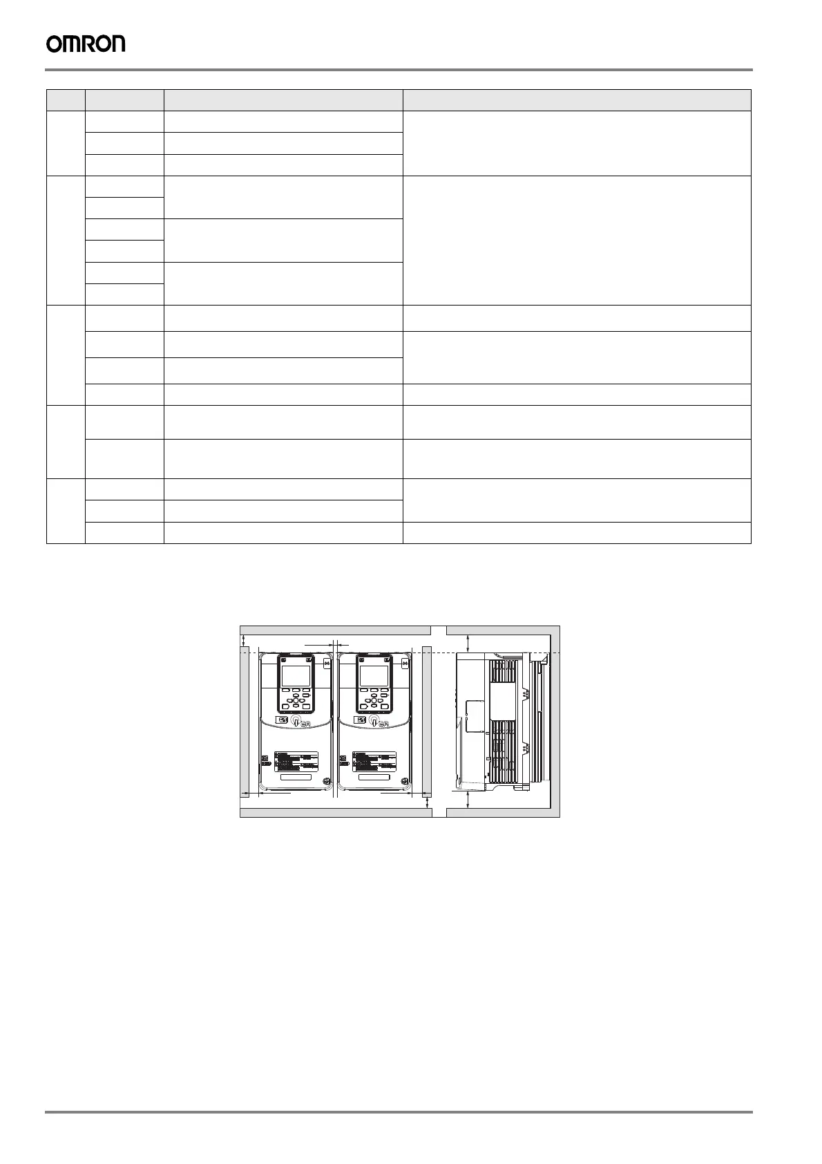
Side by side mounting
Fault relay
output
1NO
N.O. output Relay output
30 VDC, 10 mA to 1 A
250 VAC, 10 mA to 1 A
Min. load: 5 V, 10 mA (Reference value)
1NC
N.C. output
1CM
Digital output common
MFDO
*3
2NO
MFDO
(During Run)
Relay output
30 VDC, 10 mA to 1 A
250 VAC, 10 mA to 1 A
Min. load: 5 V, 10 mA (Reference value)
2CM
3NO
MFDO
(Zero Speed)
3CM
4NO
MFDO
(Speed Agree 1)
4CM
Monitor output
PO
Pulse train output
(Output frequency)
32 kHz max.
A01
MFAO1
(Output frequency)
Select voltage or current output:
0 to 10 V / 0 to 100 %
-10 to 10 V / -100 to 100 %
4 to 20 mA
A02
MFAO2
(Output current)
A0V
Monitor common
0 V
External power
supply input
E24V External 24 V power supply input Supplies backup power to the drive control circuit, keypad and option board.
21.6 to 26.4 VDC, 700 mA
A0V
External 24 V power supply ground 0 V
MEMOBUS/
Modbus
*4
RS485+
Communication input/output (+) MEMOBUS/Modbus communication protocol
Use an RS-485 cable to connect the inverter
Maximum 115.2 kbps
RS485-
Communication output (-)
A0V
Shield ground 0 V
*1. Do not close the circuit between D24V and D0V terminals. Failure to obey will cause damage to the drive.
*2. Do not close the circuit between HC and D0V terminals. Failure to obey will cause damage to the drive.
*3. Do not set functions that frequently switch ON/OFF to MFDO because this will decrease the performance life of the relay contacts.
*4. Select DIP switch S2 to ON to enable the termination resistor in the last drive in a MEMOBUS/Modbus network.
Type Terminal
Name Function (Signal level)
120 mm
120 mm
2 mm
30 mm 30 mm
50 mm
50 mm
I175E-EN-01+Q2A+Datasheet.fm Seite 16 Montag, 26. März 2018 3:18 15

 Loading...


