Q2A 15
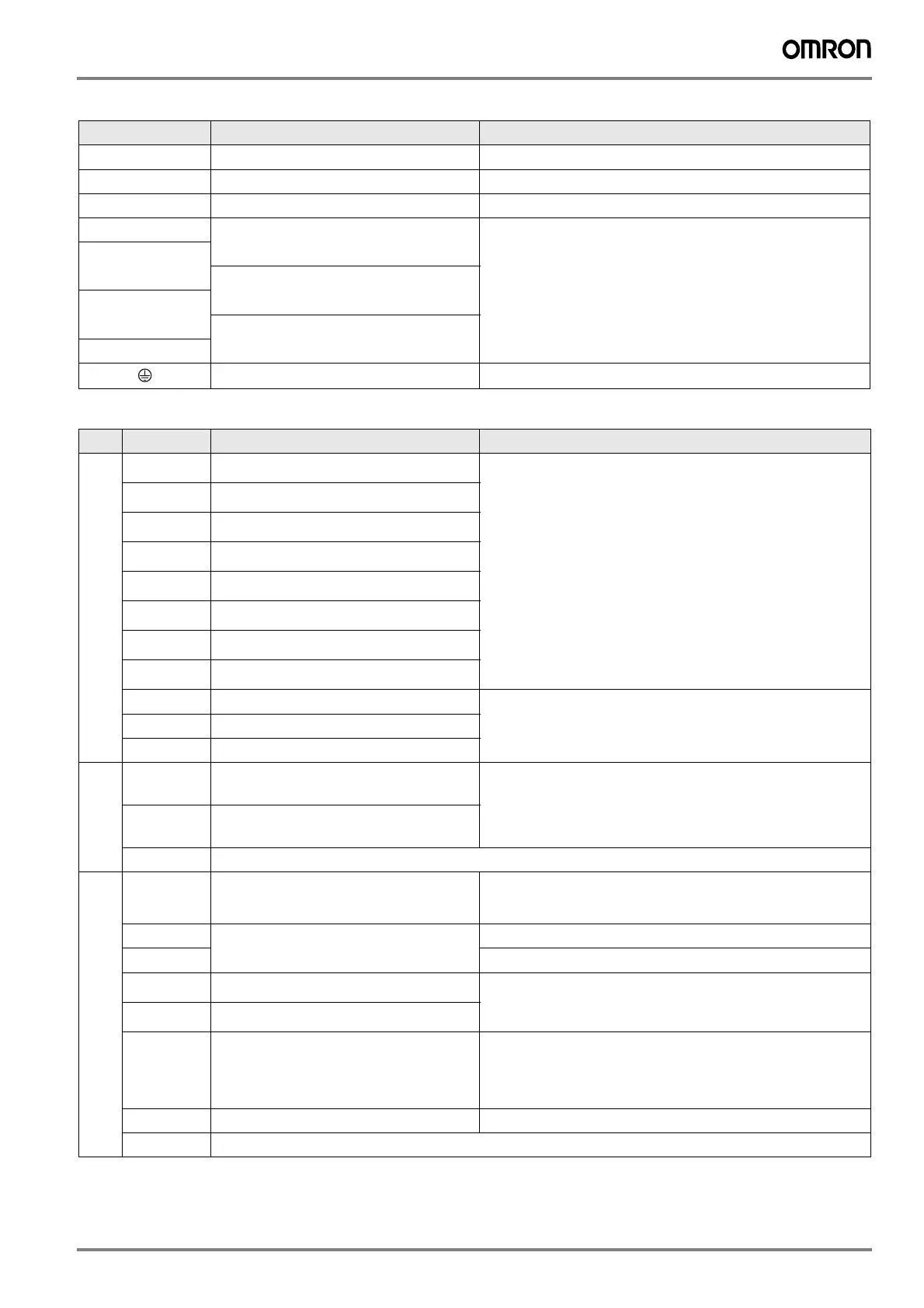
Main circuit
Control circuit
Terminal Name Function
R/L1, S/L2, T/L3
Main circuit power supply input Used to connect a power supply
U/T1, V/T2, W/T3
Inverter output Used to connect a motor
B1, B2
Braking resistor connection
To connect a braking resistor or braking resistor unit
+2
DC reactor connection
(4002 to 4044 models)
To connect peripheral devices like DC power input, braking unit or DC reactor
+1
DC power supply input
-
Braking unit connection
(4208 to 4675 models)
+3
C class grounding (10 Ω or less) To ground the inverter
Type Terminal
Name Function (Signal level)
Digital input signals
DI1
MFDI selection 1
(ON: Forward run, OFF: Stop)
Photocupler
24 V, 6 mA
Install the wire jumpers between DIC-D24V and DIC-D0V terminals to set the
MFDI power supply.
• SINK mode: Install a jumper between SC and SP terminals.
• SOURCE mode: Install a jumper between SC and SN terminals.
• External power supply: No jumper necessary.
DI2
MFDI selection 2
(ON: Reverse run, OFF: Stop)
DI3
MFDI selection 3
(External fault (N.O.))
DI4
MFDI selection 4
(Fault reset)
DI5
MFDI selection 5
(Multi-step speed reference 1)
DI6
MFDI selection 6
(Multi-step speed reference 2)
DI7
MFDI selection 7
(Jog command)
DI8
MFDI selection 8
(Baseblock command (N.O.))
D0V
*1
MFDI power supply 0 V
MFDI power supply, 24 V (max. 150 mA)
DIC
MFDI selection common
D24V1
MFDI power supply +24 VDC
Safe Disable
input
H1
Safe Disable input 1
Remove the jumper between H1-HC and H2-HC terminals to use the Safe Disable
input.
24 V, 6 mA
ON: Normal operation, OFF: Coasting motor
Internal impedance: 4.7 kΩ
Minimum OFF time of 2 ms
H2
Safe Disable input 2
HC
*2
Safe Disable function common
Master frequency
reference
PI
Pulse train input
Response frequency: 0 to 32 kHz
H level duty and voltage: 30 to 70%, 3.5 to 13.2 V
L level voltage: 0 to 0.8 V
Input impedance: 3 kΩ
+10V
Power supply for frequency setting
+10.5 V (allowable current max. 20 mA)
-10V
-10.5 V (allowable current max. 20 mA)
AI1
MFAI1
(Frequency reference)
• Voltage input or current input:
-10 V to + 10 V / -100 to +100 %
0 to 10 V / 100 % (input impedance: 20 kΩ)
4 to 20 mA / 100 %, 0 to 20 mA / 100 % (input impedance: 250 Ω)
AI2
MFAI2
(Frequency reference bias)
AI3
MFAI3/PTC input
(Auxiliary frequency reference)
• Voltage input or current input:
-10 V to + 10 V / -100 to +100 %
0 to 10 V / 100 % (input impedance: 20 kΩ)
4 to 20 mA / 100 %, 0 to 20 mA / 100 % (input impedance: 250 Ω)
• PTC input (Motor overheat protection)
A0V
Frequency reference common
0 V
GND
Connecting shielded cable
I175E-EN-01+Q2A+Datasheet.fm Seite 15 Montag, 26. März 2018 3:18 15

 Loading...


