!
!
61
3-5 Wiring I/O Units
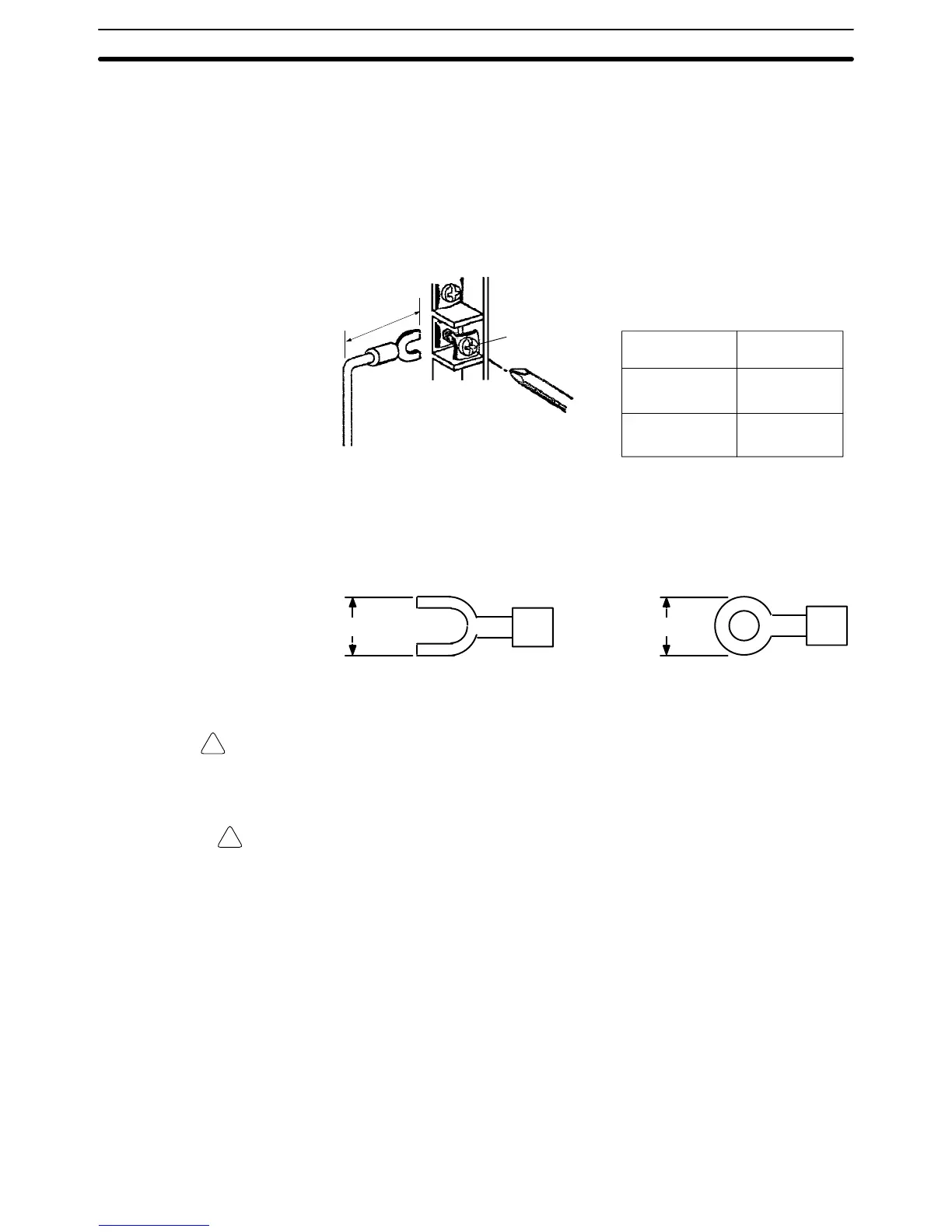
Connect
the I/O Devices to the I/O Units using A
WG 22 lead wire (cross-section
-
al area: 0.3 mm
2
) for 19-terminal terminal blocks and AWG 22 to 18 lead wire
(cross-sectional
area: 0.3
to 0.75 mm
2
) for 10-terminal terminal blocks. The ter
-
minals have screws with 3.5-mm diameter heads and self-raising pressure
plates.
Connect the lead wires to the terminals
as shown. T
ighten the screws to a
torque of 0.8 N S m.
M3.5 screw
T
ightening torque: 0.8 N
S m
A
Terminal block
A
20-terminal
Terminal block
38-terminal
Terminal block
25 mm max.
16.5 mm max.
Use crimp terminals for wiring. Do not connect bare stranded wires directly to
terminal blocks. Use M3.5 screws for tightening crimp terminals.
7
mm max.
7 mm max.
WARNING Always attach crimp terminals to the wires to ensure proper connection.
Connecting loose wires can cause fires.
Caution Abide
by the following precautions when wiring the I/O Units. Failure to abide by
these precautions my cause faulty operation or damage to the Unit.
• Be
sure that no wire clippings or other foreign materials enter
the Units when
wiring.
• Check and recheck all wiring before supplying power to the system.
• Check and recheck terminal block before mounting them to the Unit.
Note 1. Putting I/O lines and high-tension lines or power lines in the same duct or
conduit
may cause the I/O lines to be af
fected by noise. This may cause a
malfunction in the Unit or may damage the Unit or I/O devices.
2. Use
reinforced insulation or double insulation on the DC power supply con
-
nected to DC I/O Units when complying with EC directives (low voltage).
3. Use
separate
power supplies for Relay Output Units and DC I/O Units when
complying with EC directives (low voltage).
Wiring I/O Units Section 3-5
 Loading...


