64
If
the leakage current is less than 1.3 mA, there should be no problem.
If the leak
-
age
current is greater than 1.3 mA, determine the value and rating for the bleed
-
er resistor using the following formulas.
I = leakage current in mA
7.2
2.4 x I - 3
R =
kW max.
W =
2.3
R
W min.
where
I = leakage current in mA
R = Bleeder resistance (kW)
W = Bleeder resistor wattage (W)
Output Units
Output Short Protection Output devices and Output Units can be damaged if the load connected to an
output
terminal is shorted. Attach a fuse to the output circuit to protect your
sys
-
tem.
A fuse is recommended even if the
Output Unit is provided with an internal
fuse
(e.g., T
ransistor and T
riac Output Units), to increase easy of maintenance
and provide extra protection.
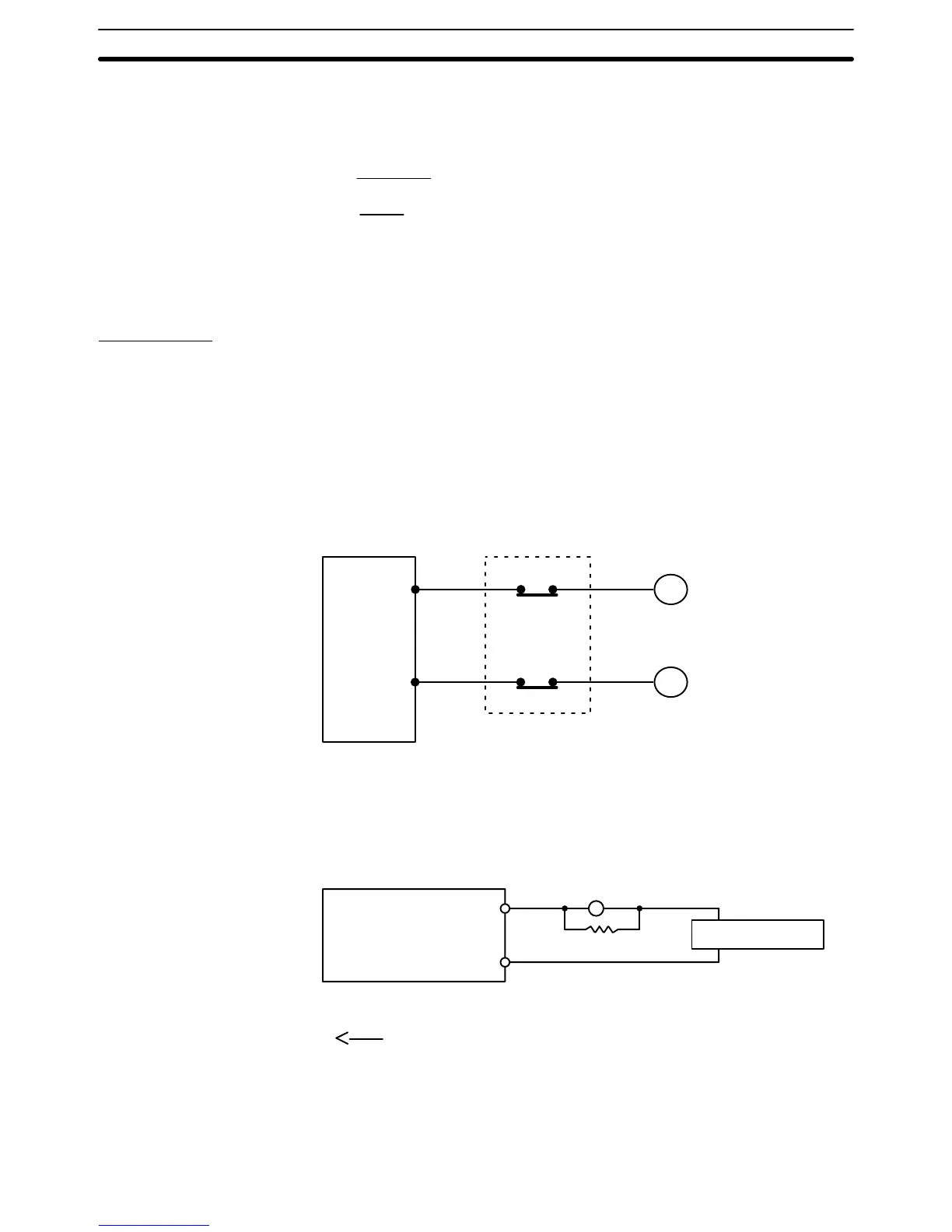
Interlock Circuits When
the PC controls an
operation such as the clockwise and counterclockwise
operation
of a motor
, provide an external interlock such as the one shown below
to prevent both the forward and reverse outputs from turning ON at the same
time.
PC
MC2
MC1
00501
00502
MC1
MC2
Motor clockwise
Motor counterclockwise
Interlock circuit
This circuit prevents outputs MC1 and MC2 from both being ON at the same
time.
Even if the PC is programmed improperly or malfunctions, the motor is pro
-
tected.
Output Leakage Current If
a transistor or triac Output Unit is
used to drive a low voltage load, the leakage
current may prevent the output device from turning OFF. To prevent this, con-
nect
a bleeder resistor in parallel with the load as shown in the following table.
PC
Load
power supply
OUT
COM
Bleeder resistor
L
R
Select the bleeder resistor using the following formula.
E
ON
I
R
where
I = leakage current in mA
R = Bleeder resistance (kW)
Eon = ON voltage of the load
Wiring I/O Units Section 3-5
 Loading...


