in carburetor and measure fuel pump pressure
developed. Pressure should be between 2 and
3
psi with gauge held
16
inches above fuel pump.
A low pressure reading indicates extreme wear in one
part or some wear in all parts; overhaul or replace the
pump. If the reading is above maximum, the
diaphragm is probably too tight or the diaphragm
spring too strong. This can also be caused by fuel
seeping under the diaphragm retainer nut and
between the diaphragm layers, causing a bulge in the
diaphragm. Overhaul the pump and replace the
defective parts.
Low pressure with little or no pressure leak after
pumping stops indicates a weak or broken spring or
worn linkage, and in most cases the pump should be
replaced.
Removal and Disassembly:
1.
2.
3.
4.
Remove pump inlet and outlet (Figure 16).
Remove two capscrews holding pump to engine
and lift it off.
Notch pump cover and body with a file for
assembly in same relative position, and remove
six screws holding them together.
Tap body with a screwdriver to separate two
parts. Don’t pry them apart; this may damage
diap h rag m.
Lift out diaphragm assembly and diaphragm
spring.
Repair:
Fuel pump failure
is
usually due to a leaking
diaphragm, valve or valve gasket. A kit is available for
replacement of these parts. Because the extent of
wear cannot easily bedetected, replace all parts in the
kit. If the diaphragm is broken or leaks, check for
diluted crankcase oil. Occasionally, failure is due to a
broken or weak spring, or wear in the linkage. In this
case, install a new pump.
Assembly:
1.
Before installing a new diaphragm, soak it in fuel.
Insert diaphragm spring and soaked diaphragm
into pump body.
2.
Compress rocker spring and install between body
and rocker arm.
3.
Assemble cover to body with notch marks lined
up. Install the screws but don’t tighten. Push the
rocker arm in full stroke and hold
in
this position
to flex diaphragm.
The diaphragm must be flexed, or
it
will
deliver too much fuel
pressure.
then release rocker arm.
test.
4.
Tighten cover screws alternately and securely,
5.
Install pump on the engine and repeat pressure
Choke
(Gasoline
Fuel
System)
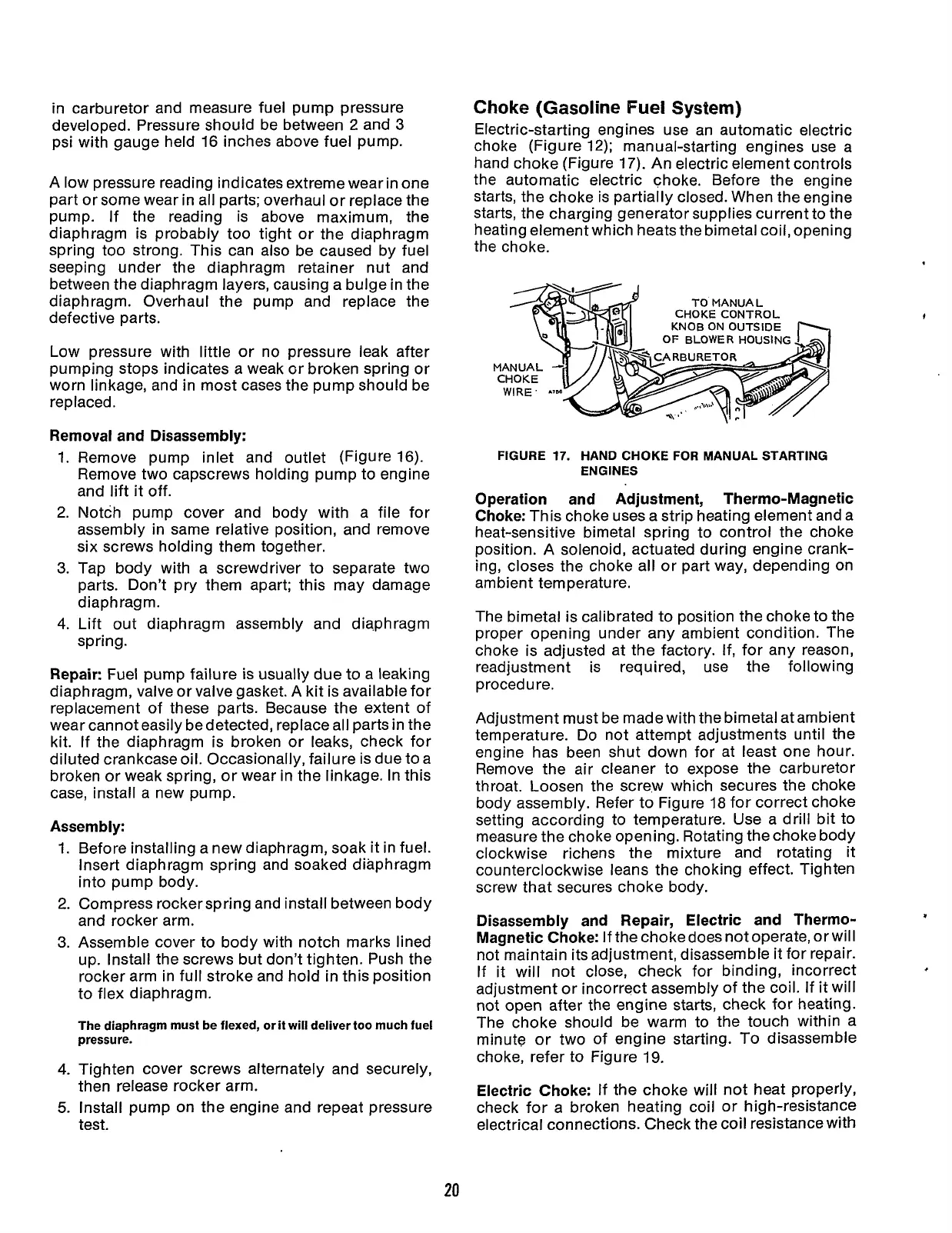
Electric-starting engines use an automatic electric
choke (Figure 12); manual-starting engines use a
hand choke (Figure
17).
An electric element controls
the automatic electric choke. Before the engine
starts, the choke is partially closed. When the engine
starts, the charging generator supplies current to the
heating element which heats the bimetal coil, opening
the choke.
KNOB
ON
OUTSIDE
OF
BLOWER
HOUSING
-m
FIGURE
17.
HAND CHOKE
FOR
MANUAL STARTING
ENGINES
Operation and Adjustment, Thermo-Magnetic
Choke:
This choke uses a strip heating element and a
heat-sensitive bimetal spring to control the choke
position. A solenoid, actuated during engine crank-
ing, closes the choke all or part way, depending on
ambient temperature.
The bimetal is calibrated to position the choke to the
proper opening under any ambient condition. The
choke is adjusted at the factory. If, for any reason,
readjustment is required, use the following
procedure.
Adjustment must be made with the bimetal atambient
temperature.
Do
not attempt adjustments until the
engine has been shut down for at least one hour.
Remove the air cleaner to expose the carburetor
throat. Loosen the screw which secures
the
choke
body assembly. Refer to Figure
18
for correct choke
setting according to temperature. Use a drill bit to
measure the choke opening. Rotating the choke body
clockwise richens the mixture and rotating it
counterclockwise leans the choking effect. Tighten
screw that secures choke body.
Disassembly and Repair, Electric and Thermo-
Magnetic Choke:
If the choke does not operate, or will
not maintain its adjustment, disassemble it for repair.
If it will not close, check for binding, incorrect
adjustment or incorrect assembly of the coil. If it will
not open after the engine starts, check for heating.
The choke should be warm to the touch within a
minute or two of engine starting. To disassemble
choke, refer
to
Figure
19.
Electric Choke:
If the choke will not heat properly,
check for a broken heating coil or high-resistance
electrical connections. Check the coil resistance with
.
20
Redistribution or publication of this document,
by any means, is strictly prohibited.
 Loading...


