Therrno-Magnetic
Choke:
If choke will not heat
properly, check for broken heater wire, high-
resistance connections or broken lead wires to the
bimetal and heater assembly. With the element at
room temperature, check the heater resistance with
an ohmmeter. The resistance should be about 30.6 to
37.4
ohms for a
12
volt system.
If the heater is
defective, replace it with a new one. When the start
button is engaged, the solenoid should cause the
spring-loaded armature to contact the solenoid core.
If this does not occur, check for broken lead wires or a
defective solenoid coil. There must be slack in the
lead wires between the choke body and the bimetal
and heater assembly. The solenoid coil resistance
should be
2.09
to 2.31 ohms in a 12 volt system.
When replacing the cover on the thermostat and
heater assembly, be certain that the choke heater
lead wires have been correctly installed in the choke
housing. improper replacement of the lead wires can
cause the choke assembly to malfunction.
The wires enter the choke assembly through a small
notch that
is
cut in the edge of the housing.
A
cover
holds the wires in place and prevents movement
when tightened. When properly installed, the lead
wires will hang freely under the bimetal coil when the
choke is in either the open or closed position. The
end of the heater wire sleeve should be located from
118
inch inside the choke housing to flush with the
inside wall.
When assembling the thermo-magnetic choke, the
bimetal and heater assembly is connected as follows:
1.
Lead tagged G‘goes to ground terminal on coil
2. Lead tagged
H
goes to either
H1
terminal on
solenoid.
solenoid core.
GASOLINE CARBURETOR
The gasoline carburetor is a horizontal draft type. It
consists of three major sections: the bowl and float,
idle circuit, and load circuit.
Fuel enters the carburetor through the valve (Figure
20) and passes into the float chamber. The float
controls fuel level in the bowl by closing the inlet valve
when fuel reaches a certain height and opening it
when the fuel level drops.
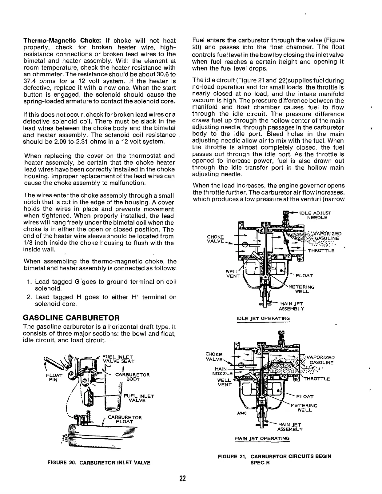
The idle circuit (Figure 21 and 22)suppliesfuel during
no-load operation and for small loads. the throttle is
nearly closed at no load, and the intake manifold
vacuum is high. The pressure difference between the
manifold and float chamber causes fuel to flow
through the idle circuit. The pressure difference
draws fuel up through the hollow center of the main
adjusting needle, through passages in the carburetor
body to the idle port. Bleed holes
in
the main
adjusting needle allow air to mix with the fuel. When
the throttle is almost completely closed, the fuel
passes out through the idle port.
As
the throttle is
opened
to
increase power, fuel is also drawn out
through the idle transfer port in the hollow main
adjusting needle.
When the load increases, the engine governor opens
the throttle further. The carburetor air flow increases,
which produces a low pressure at the venturi (narrow
I
CHOKE
VALVE
IDLE ADJUST
IDLE
JET
OPERATING
M
MAIN
JET
OPERATING
FIGURE
20.
CARBURETOR INLET VALVE
22
FIGURE
21.
CARBURETOR CIRCUITS BEGIN
SPEC
R
Redistribution or publication of this document,
by any means, is strictly prohibited.
 Loading...


