3. Position a bearing half
in
each connecting rod.
Be
sure there is no dirt under bearing. This could
cause high spots and early bearing failure.
4. Oil cylinder walls and pistons. Install each piston
in proper cylinder using a suitable installer. Each
assembly should be installed with
“V”
mark on
piston toward front
of
engine. The word ‘!Front”
may be found on some piston tops. See Figure 75.
5.
Position each connecting rod on the crankshaft,
oil the journal and install its rod cap with bearing
half. When installing the rod cap, position
so
the
raised witness mark on the forging matches the
mark on the connecting rod (Figure 76).
6. Tighten connecting rod capscrews to specified
torque (27-29 ft. Ibs.).
FIGURE
76.
CONNECTING
ROD
WITNESS
MARKS
7. Crank engine over by hand to see that all bearings
8.
Install
oil
base with a new gasket. Install cylinder
are free.
heads.
Break-In Period:
Whenever new rings or pistons are
installed, or the cylinder refinished, the engine must
be run-in before regularoperation. Run theengine for
15
to
20
minutes at no load, about 1/2 hour at 1/3 load
and
2
to
3
hours at 2/3 load. Then resume regular
operation.
Avoid light loads during the balance of the break-in
period to best seat rings for oil control.
ENGINE
DISASSEMBLY
During engine disassembly, observe the following
order (Le., Flywheel, Gear Cover, etc.).
As
dis-
assembly progresses, the order may be changed
somewhat as will be self-evident.
The engine assembly procedure is the reverse of
disassembly. Any special assembly instructions for a
particular component are included. When reassembl-
ing, check for special assembly instructions or
procedures.
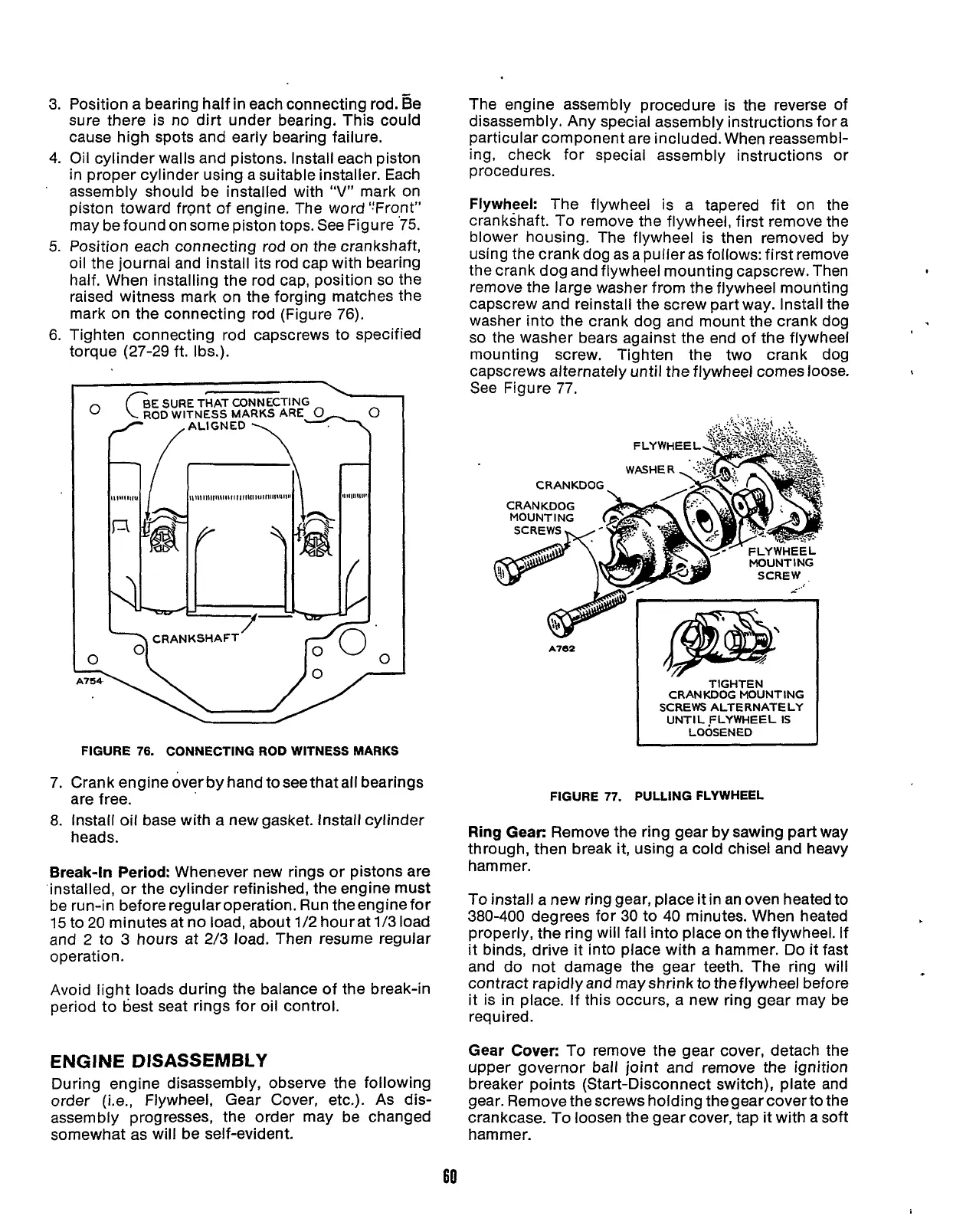
Flywheel: The flywheel is a tapered fit on the
crankshaft.
To
remove the flywheel, first remove the
blower housing. The flywheel is then removed by
using the crank dog as a puller as follows: first remove
the crank dog and flywheel mounting capscrew. Then
remove the large washer from the flywheel mounting
capscrew and reinstall the screw part way. Install the
washer into the crank dog and mount the crank dog
so
the washer bears against the end of the flywheel
mounting screw. Tighten the two crank dog
capscrews alternately until the flywheel comes loose.
See Figure 77.
\
..
CRANKDOG
CRANKDOG
MOUNT
I
NG
SCREW
_..‘
Y
A762
I
1Fy:
TIGHTEN
CRANKDOG MOUNTING
I
SCREWS ALTERNATELY
UNTIL
FLYWHEEL
IS
LOOSENED
FIGURE
77.
PULLING FLYWHEEL
Ring Gear:
Remove the ring gear by sawing part way
through, then break it, using a cold chisel and heavy
hammer.
To
install a new ring gear, place it in
an
oven heated to
380-400 degrees for
30
to 40 minutes. When heated
properly, the ring will fall into place on the flywheel. If
it binds, drive it into place with a hammer. Do it fast
and do not damage the gear teeth. The ring will
contract rapidly and may shrink
to
the flywheel before
it is
in
place. If this occurs, a new ring gear may be
required.
Gear Cover:
To remove the gear cover, detach the
upper governor ball joint and remove the ignition
breaker points (Start-Disconnect switch), plate and
gear. Remove the screws holding thegear coverto the
crankcase. To loosen the gear cover, tap it with a soft
ham mer.
60
Redistribution or publication of this document,
by any means, is strictly prohibited.
 Loading...


