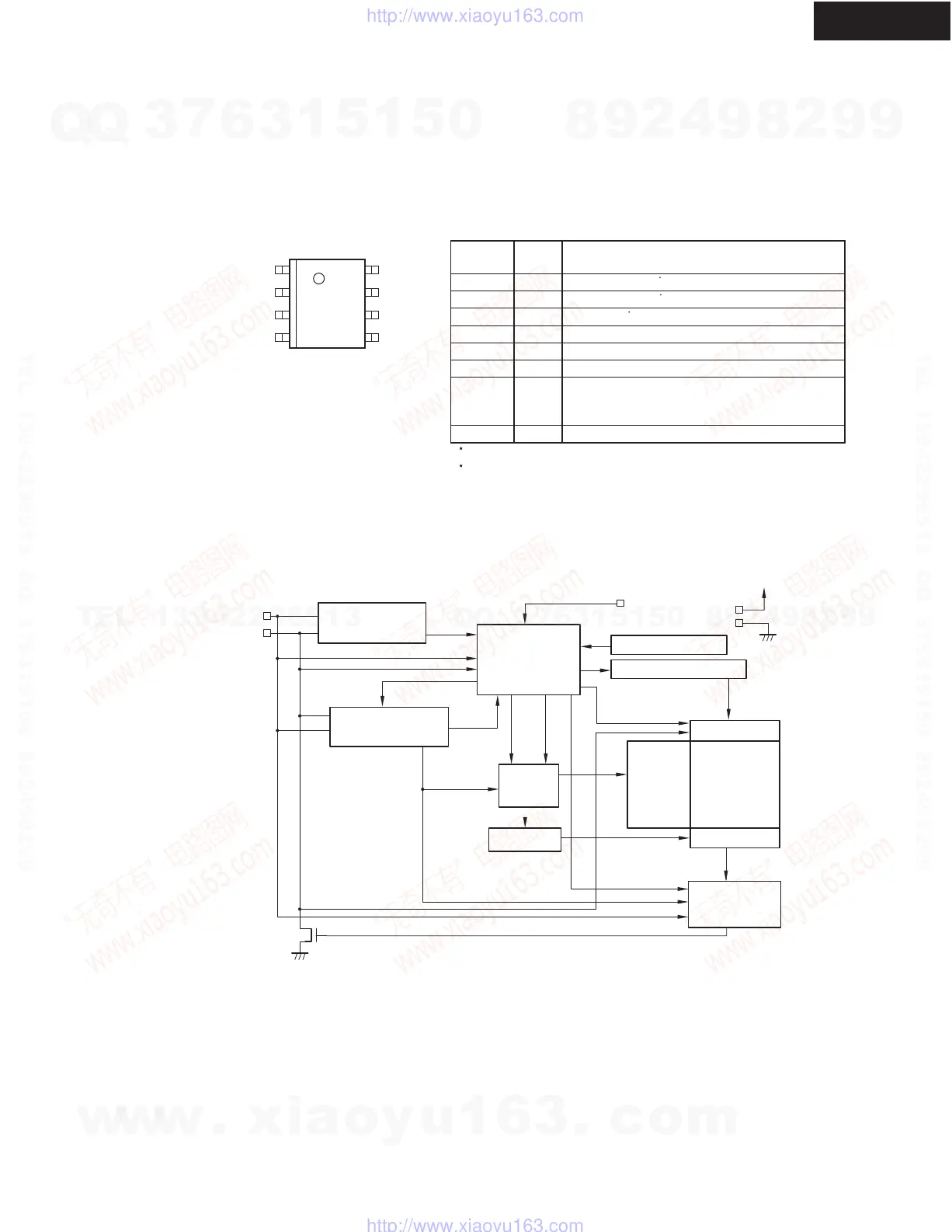
PIN ASSIGNMENT
1
2
3
4
8
7
6
5
NC
NC
A2
GND
V
CC
WP
SCL
SDA
8-Pin SOP
Top view
Pin
Number
Pin
Name
Function
1
2
3
4
5
6
7
8
NC
NC
A2
GND
SDA
SCL
WP
V
CC
No connection
No connection
TES pin
Ground
Serial data input/output
Serial clock input
Write protection input
connected to Vcc: Protection valid
Connected to GND: Protection invalid
Power supply
1.
2.
1
2
1
Connected to GND or Vcc.
Connected to GND.
BLOCK DIAGRAM
VCC
GND
WP
Serial Clock
Controller
Voltage Detector
High-Voltage Generator
Data Register
E PROM
2
X Decoder
Selector
Data Output
ACK Output
Controller
Dout
Y Decoder
R / W
LOAD
INC
Address
Counter
LOAD
COMP
Device Address
Comparator
Start / Stop
Detector
SCL
SDA
Din
A-5VL
IC BLOCK DIAGRAM/ TERMINAL DESCRIPTION
Q703: S-24CS16A0I-J8V1G (2-Wire CMOS 16k bit E ROM)
2
w
w
w
.
x
i
a
o
y
u
1
6
3
.
c
o
m
Q
Q
3
7
6
3
1
5
1
5
0
9
9
2
8
9
4
2
9
8
T
E
L
1
3
9
4
2
2
9
6
5
1
3
9
9
2
8
9
4
2
9
8
0
5
1
5
1
3
6
7
3
Q
Q
TEL 13942296513 QQ 376315150 892498299
TEL 13942296513 QQ 376315150 892498299
http://www.xiaoyu163.com
http://www.xiaoyu163.com
 Loading...