A-5VL
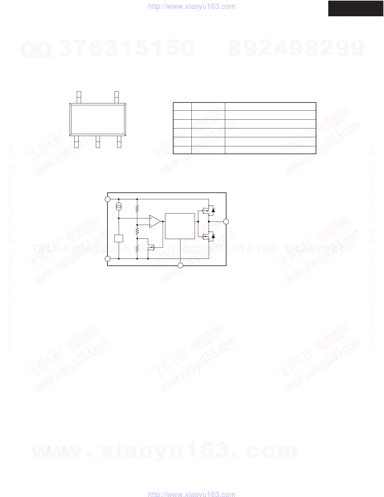
IC BLOCK DIAGRAM/ TERMINAL DESCRIPTION
123
45
Q951: S-80127CNMC-JKM VOLTAGE DETECTOR (12.7V N-ch open drain, Active L: out)
PIN CONFIGURATION
Top view
PIN DESCRIPTION
No.
1
2
3
4
5
Symbol
DS
VSS
NC
OUT
VDD
Description
ON/OFF switch for delay time
GND
Non-connection
Voltage detection output pin
Voltage input pin
*1
*1. NC pin is electrically open.
Oscillator
counter
timer
VREF
DELAY CIRCUIT
VDD
VSS
DS
OUT
BLOCK DIAGRAM
w
w
w
.
x
i
a
o
y
u
1
6
3
.
c
o
m
Q
Q
3
7
6
3
1
5
1
5
0
9
9
2
8
9
4
2
9
8
T
E
L
1
3
9
4
2
2
9
6
5
1
3
9
9
2
8
9
4
2
9
8
0
5
1
5
1
3
6
7
3
Q
Q
TEL 13942296513 QQ 376315150 892498299
TEL 13942296513 QQ 376315150 892498299
http://www.xiaoyu163.com
http://www.xiaoyu163.com
 Loading...