5 4 3
2
1
6
D
C
A
B
D
C
A
B
5 4 3
2
1
6
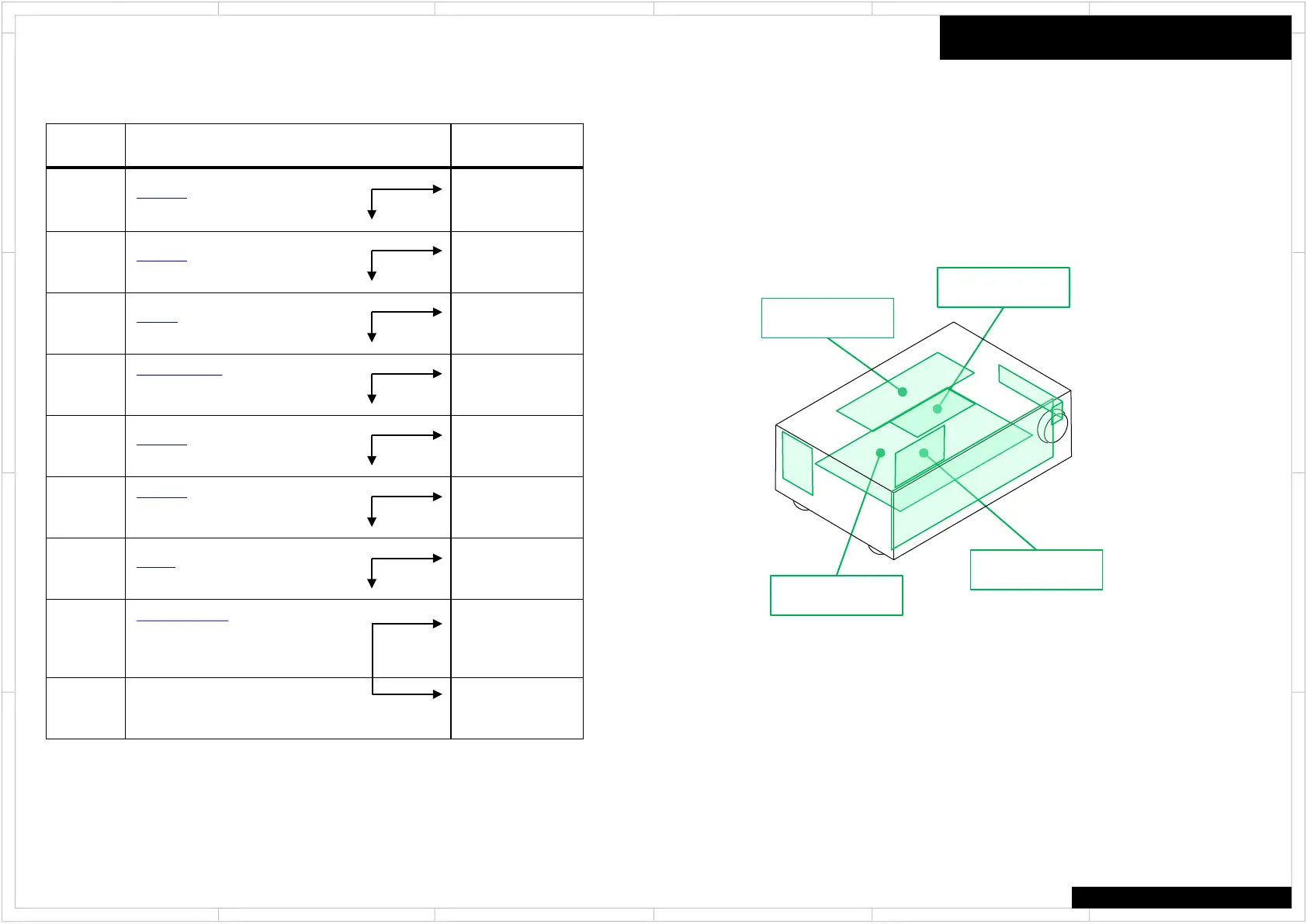
Trouble Shoot
Here the trouble shoot which focuses on the hardware troubles regarding PCB assembly is explained.
Of course, with actual repair there are also troubles due to damaged Power Transformer, Wiring, soldering etc. in addition to PCB assembly.
No Sound (HDMI in)
TX-NR609
TX-SR343/444/HT-R494
Process Check Point Damaged PCB
1
P2801B (BAPRC-1758)
● No.2 pin : +15V
BAVD-1735
2
P2800B (BAPRC-1758)
● No.7 pin : +3.3V
BAPRC-1758
3
R6690 (BAAF-1712)
● : +21.5V
BAAF-1712
4
J4036, J4000 (BAAF-1712)
● J4000 : +15V
● J4036 : -15V
BAAF-1712
5
P8002A (BAPRC-1758)
● No.11 pin : +3.2V
BAAF-1712
6
P8002A (BAPRC-1758)
● No.2 pin : Check signal
● No.4 pin : Check signal
BAPRC-1758
7
J4051 (BAAF-1712)
● : Check signal
BAAF-1712
8
Q6050, Q6060 (BAAF-1712)
Check signal
● Q6050(base) : Check signal
● Q6060(base) : Check signal
BACLA-1734
9 BAAF-1712
No Good
OK
No Good
OK
No Good
OK
No Good
OK
No Good
OK
No Good
OK
No Good
OK
No Good
OK
BAPRC-1758
BAAF-1712
BACLA-1734
BAVD-1735
●Each voltage is shown as the reference value.
Value error : Plus or minus 15%
 Loading...