IG-183-EN version 06; 31/03/2020
24
Installation
General instructions
cgm.3 system: medium voltage SF
6
gas-insulated
cubicles up to 38 kV according to IEEE and CSA standards
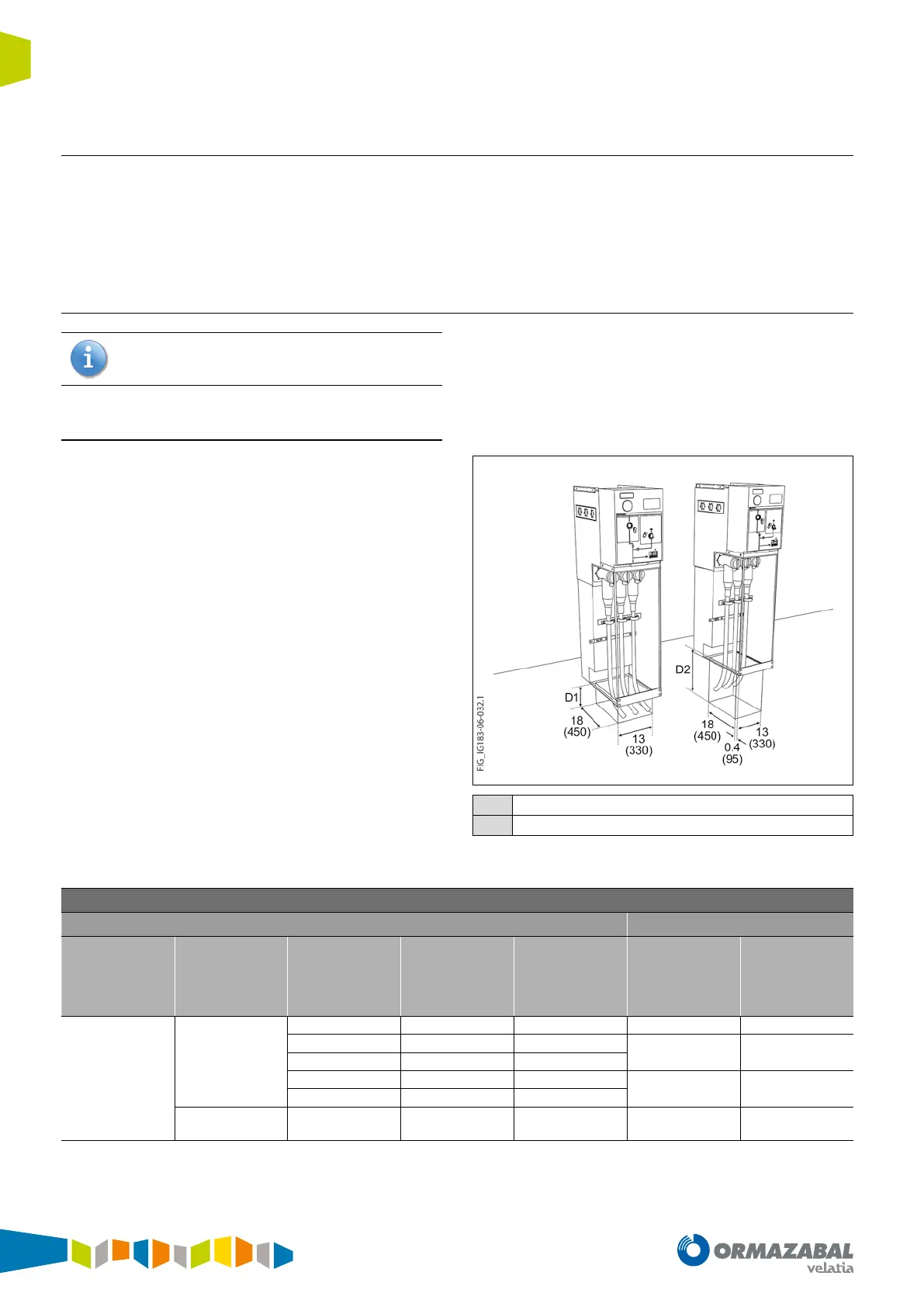
4.3. Recomended cable trenchs
Recomended mínimum dimensions according to the
dimensions of the trench used during the test according
to the IEC 62271-200 standard. Depending on the radius of
curvature of the cables used these dimensions may vary.
4.3.1. Cubicles with gas tank internal arc up to 20 kA - 0,5 s
Tests conducted with a test current of 21 kA. Consider
in each case the cable used in each installation.
Feeder, busbar raise and cable raise functions
The mínimum dimensions of the cable trench depend of
the mínimum radius of curvature of the cables used:
D1
Frontal or rear cables incoming or outgoing
D2
Lateral cables incoming or outgoing
Figure 4.3. Dimensions [mm] of the cable trench for cgm.3-l, cgm.3-rb
and cgm.3-rc
Necessary cable trench for feeder, busbar raise and cable raise functions
Cable data Minimum depth
Cable
insulation
Cable type
Cable section
[mm
2
]
Cable
diameter
[mm]
Indicative
radius of
curvature*
[mm]
D1
[mm]
D2
[mm]
Dry insulation
One-core
18/30 kV
< 150 41 555 200 500
185 43 590
200 550
240 45.2 640
300 47.5 685
300 660
400 50.5 745
Three-core
18/30 kV
< 150 92.7 805 650 650
* Check with the cable used manufacturer’s data.
Table 4.2. Necessary cable trench for feeder, busbar raise and cable raise functions
 Loading...