Display status, click to choose "Disconnect", "Install USB Driver" or "Connect LAN". Refer to the
instruction of the status after this list.
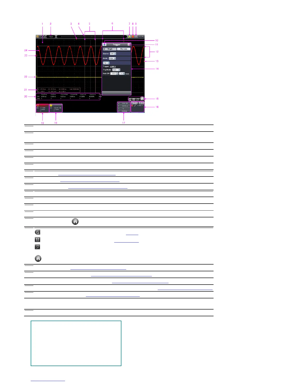
The red pointer indicates the horizontal position for the trigger
The pointer indicates the trigger position in the internal memory
Measure time with cursors
The two yellow dotted lines indicate the size of the viewing expanded window
Auto set, see 15.How to Use Executive Buttons
Run/Stop, see 15.How to Use Executive Buttons
Single Trigger, see 15.How to Use Executive Buttons
Measure voltage with cursors
The red pointer shows the trigger level position for CH1 (yellow for CH2). It can be dragged up and down.
Function menu, click to show/hide
Shortcut icon of resetting to factory settings, see "Default"
Shortcut icon of exporting waveform, see "Pause&Export"
Switch Three View/One View. In the Three View di
splay mode, the left top is XY mode widow, the
right top is FFT window.
Show/hide Function menu
Trigger window, see 4.How to Set the Trigger System
Sample and Period window, see 3.How to Set the Horizontal System
18/19. Channel window of CH2 and CH1, see 2.How to Set the Vertical System
Display the measured type and value of the corresponding channel, see 6.How to Measure Automatically
Cursor measure window, see 8.How to Measure with Cursors
22/23. The yellow pointer shows the grounding datum point (zero point position) of the CH2 waveform. If
the pointer is not displayed, it means that this channel is turned off. (Red pointer is for CH1)
Space: Run/Stop
Enter: Auto set
Q:
The voltage division of Channel 1 decreases one
level
A: The voltage division o
f Channel 1 increases one
level
W: The voltage division of Channel 2 decreases
 Loading...