English
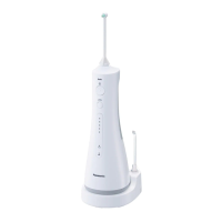
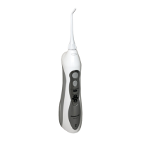
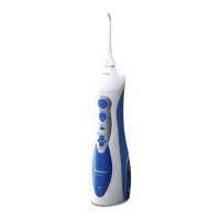
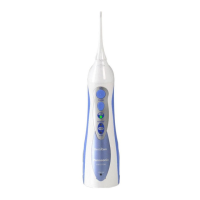
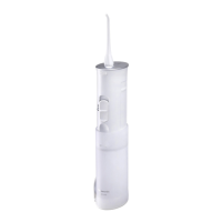
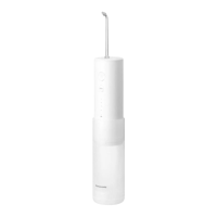
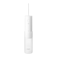
A Main unit
a
Power switch (
)
b
Level switch
c
Water pressure level LED
indicator (1~5 levels)
d
Low battery indicator (blue)
e
Charge status indicator (red)
f
Nozzle release button
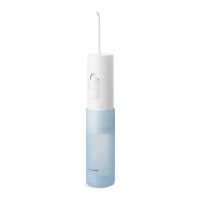
g
Water tank (Inside)
h
Water tank cap
i
Suction hose
j
Filter
k
Bottom cover release button
l
Bottom cover
B ACadaptor(RE7-87)
(The shape of the power
plug differs depending
on the area. One of
the power supply units
speci ed is provided with
this appliance.)
m
Adaptor
n
Power plug
o
Cord
p
Appliance plug
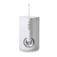
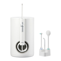
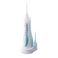
C Chargingstand(RC8-4)
q
Charging plug
r
Nozzle stand
s
Screw holes for wall mounting
The charger can be mounted
on a wall using two wood
screws.
t
Stand socket
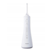
D Nozzle(×2)
•
The nozzle is a consumable.
u
Nozzle
v
Nozzle Handle
w
Identi cation ring
Accessory
E 2 screws
A B
C
D
E
b
c
a
h
g
f
i
j
k
l
t
q
s
wvu
m
o
p
n
r
e
d
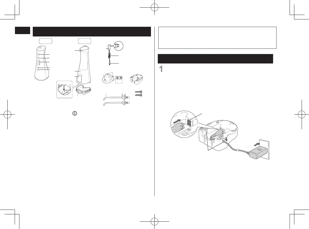
Partsidentication
Charging
1
ConnecttheACadaptor.
1
Insert the appliance plug rmly to the stand
socket.
Press the cord into either the left or right groove,
depending on where it will be placed.
•
Place the charging stand on a at and stable
surface.
Insert the adaptor into a household outlet.
3
2
1
Stand socket
Groove
Note
There may be moisture inside the main unit (water tank
and suction hose) left from the distilled water used for
product testing.
Front Back
10
EW1511.indb 10 2019/3/28 20:44:38
 Loading...