1
InstructIons
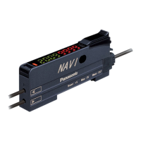
Digital Fiber Sensor Amplier
FX-501□, FX-502□, FX-505□-C2 Series
Thank you for purchasing products from Panasonic Electric Works SUNX
Co., Ltd. Please read this Instruction Manual carefully and thoroughly for
the correct and optimum use of this product. Kindly keep this manual in a
convenient place for quick reference.
WARNING
● Never use this product as a sensing device for personnel protection.
● In case of using sensing devices for personnel protection, use prod‑
ucts which meet laws and standards, such as OSHA, ANSI or IEC
etc., for personnel protection applicable in each region or country.
1
Compliance with standards
This product complies with the following standards and
regulations.
● For the EU: EMC Directive 2004/108/EC
● For the US and Canada:
ANSI/UL60947‑5‑2, CAN/CSA C22.2 No.14
● For Korea: S1‑G‑1‑2009, S2‑W‑5‑2009
* In case you require a UL listing mark or C-UL
listing mark, use a class 2 power supply unit.
2
Part description
FX-501□
1 2 3 4
56789
1
Operation indicator for sensing output (orange)
2
Digital display (green/red)
3
UP key (+) Functions:
● Teach
● Fine adjustment of the threshold value
● Select settings
4
DOWN key (–)
5
MODE key Functions:
● Select modes
● Cancel
6
SET key Functions:
● Teach
● Save selected settings
7
Mode indicator PRO mode (yellow), see page 6
8
Mode indicator CUST (custom) mode (yellow), see page 5
9
Mode indicator L /D (Light‑ON/Dark‑ON) mode (yellow)
FX-502□ and FX-505□-C2
1 2 3 4 5
67890
1,
Sensing output 1 (lit if output is active)
● Orange: Sensing output is operating
2
Sensing output 2 (lit if output is active)
● Orange: Sensing output is operating
3
Digital display (green/red)
4
UP key (+) Functions:
● Teach
● Fine adjustment of the threshold value
● Select settings
5
DOWN key (–)
6
MODE key Functions:
● Select modes
● Cancel
7
SET key Functions:
● Teach
● Save selected settings
8
Mode indicator PRO mode (yellow)
9
Mode indicator CUST (custom) mode (yellow)
0
Mode indicator L /D (Light‑ON/Dark‑ON) mode (yellow)
* To toggle the key lock function ON/OFF, press the SET and the
MODE key together for 3 seconds.
3
Mounting
Installation to a DIN rail
1. Attach the railing on the rear of the ampli‑
er to the DIN rail.
2. Push the amplier in the direction of the
arrow as illustrated so that it attaches
securely.
1.
2.
Removal from a DIN rail
1. Push the amplier forward.
2. Lift the front part of the amplier up.
1.
2.
Connecting the ber cable
* The attachments to the ber cables need to be tted BEFORE
you insert the bers into the amplier. For details, refer to the
instruction manual enclosed with the bers.
1. Snap the ber lock lever 1 down as
far as it will go.
2. Insert the ber cables slowly into the
inlets until they stop (see note).
3. Return the ber lock lever to the
original position.
2.
1.
3.
1
2
3
* With the coaxial reective type ber, such as FD-G4 or FD-FM2,
insert the single core ber cable into the inlet for the emitter 2
(inlet on the amplier is labeled “P”) and the multi-core ber
cable into the inlet for the receiver 3. If they are inserted the
wrong way round, the sensing performance will deteriorate.