10
Pro7 menu
Menu item
Default
setting
Description
Logic operation
setting
Select how two signals should be logically con‑
nected (and, or, xor). For details, refer to the table
in note 1.
The sensing output 1 of an amplier mount‑
ed to the left of this amplier is logically
connected with the sensing output 1 of this
amplier using the logical operator selected
with this menu item. The result is output
from the sensing output 1 of this amplier.
Only for FX-502□, FX-505□-C2. An input
signal from a device mounted to the left of
this amplier is logically connected with the
sensing output 1 of this amplier using the
logical operator selected with this menu
item.
Only for FX-502□, FX-505□-C2. The logical
connection takes place within this amplier.
The external input is logically connected
to the sensing output 1 using the logical
operator selected with this menu item.
Threshold value
follow‑up cycle
The incident light intensity can be monitored
for the cycle (1 to 9,999s) specied, for
example when variations in incident light
intensity are expected. When the threshold
value follow‑up cycle is set, the thresh‑
old value is adjusted according to the
shift based on the incident light intensity
detected. However, the threshold value is
not stored.
Sensing out‑
put setting
Select whether the threshold value should be fol‑
lowed when the output is OFF or when the output
is ON.
Storage cycle
setting
Select the cycle for storing threshold values in the
EEPROM. The valid range is 1 to 250 times.
Algorithm
setting
When limit teaching is used, the thresh‑
old value is modied by the shift amount.
The direction of the threshold shift differs
depending on the combination of the sens‑
ing output status and the sensing output
operation, see note 2.
When auto teaching is used, the threshold
value will be followed up when the base
condition set in “Sensing output setting” is
TRUE.
* Notes
1. The following logic applies:
Signal from other
amplier or device
Sensing output 1
of this device
Logical operator
and or xor
ON ON ON ON OFF
ON OFF OFF ON ON
OFF ON OFF ON ON
OFF OFF OFF OFF OFF
2. The direction of the threshold shift differs depending on the combination of the
sensing output status and the sensing output operation.
Sensing output
status
Sensing output
operation
Shift direction
ON Light‑ON –
ON Dark‑ON +
OFF Light‑ON +
OFF Dark‑ON –
13
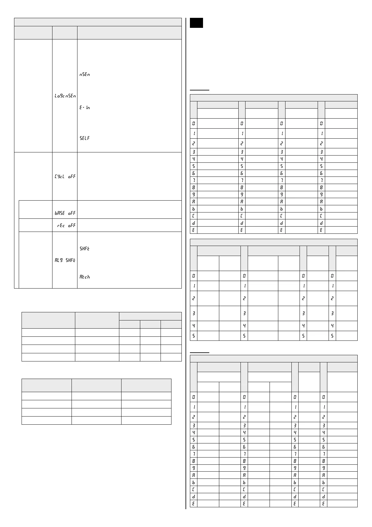
Code setting tables
The code tables list the codes for the green and the red display for each
sensor type. Note that the digit on the right side is always the rst digit. The
following abbreviations are used:
OFD OFF‑delay timer OND ON‑delay timer
ONOF ON/OFF‑delay timer OSD One‑shot timer
ONOS On‑delay/One‑shot timer
WC Window comparator mode HYS Hysteresis mode
FX-501□
Green digital display
Code
Forth digit
Code
Third digit
Code
Second digit
Code
First digit
Sensing output
operation mode
Timer operation Time delay
CUSTOM
setting
Light‑ON No timer 0.5ms
Response time
setting
Dark‑ON OFD 1ms
Emission power
setting
– OND 3ms
Hysteresis
setting
– ONOF 5ms –
– OSD 10ms –
– ONOS 30ms –
– – 50ms –
– – 100ms –
– – 300ms –
– – 500ms –
– – 1s –
– – 2s –
– – 3s –
– – 4s –
– – 5s –
Red digital display
Code
Forth digit
Code
Third digit
Code
Second
digit
Code
First digit
Copy lock
setting
Hys‑
teresis
setting
Setting items
in the digital
display
Backup
setting
Response
time set‑
ting
Sensing
output
setting
Copy lock
OFF
H‑02
Incident light
intensity
Backup
ON
H‑SP
Normal
mode
Copy lock
ON
H‑02
Incident light
intensity
Backup
OFF
FAST WC
Copy lock
OFF
H‑03
Displayed as
a percentage
Backup
ON
STD
Rising dif‑
ferential
mode
Copy lock
ON
H‑03
Displayed as
a percentage
Backup
OFF
LONG
Falling
differential
mode
Copy lock
OFF
H‑01
Peak / bottom
value
Backup
ON
U‑LG HYS
Copy lock
ON
H‑01
Peak / bottom
value
Backup
OFF
HYPR ‑
FX-502□
Green digital display
Code
Forth digit
Code
Third digit
Code
Second
digit
Code
First digit
Sensing output
operation mode
Timer operation
Timer
period
CUSTOM
setting
Sensing
output 1
Sensing
output 2
Sensing
output 1
Sensing
output 2
Light‑ON Light‑ON No timer No timer 0.5ms
Response
time setting
Light‑ON Dark‑ON OFD No timer 1ms
Emission
power setting
Dark‑ON Light‑ON OND No timer 3ms
Hysteresis
setting
Dark‑ON Dark‑ON ONOF No timer 5ms –
– – OSD No timer 10ms –
– – ONOS No timer 30ms –
– – No timer OFD 50ms –
– – No timer OND 100ms –
– – No timer OSD 300ms –
– – – – 500ms –
– – – – 1s –
– – – – 2s –
– – – – 3s –
– – – – 4s –
– – – – 5s –
 Loading...