2
4
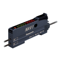
Cascading ampliers of the connector type
* Cascading is not available for FX-505□-C2.
● You can only cascade ampliers of the connector type, i.e. FX-501□
and FX‑502□.
● Make sure that the power supply is OFF while adding or removing
ampliers of the connector type.
● If you cascade 2 or more ampliers, make sure to mount them on a
DIN rail. Refer to “3 Mounting” for details.
● For each amplier using a main connection cable you can install a
maximum of 11 additional ampliers using sub cables.
● If you connect 2 or more ampliers of the connector type in cas‑
cade, use the sub cable (optional) for the second connector‑type‑
type amplier and all after.
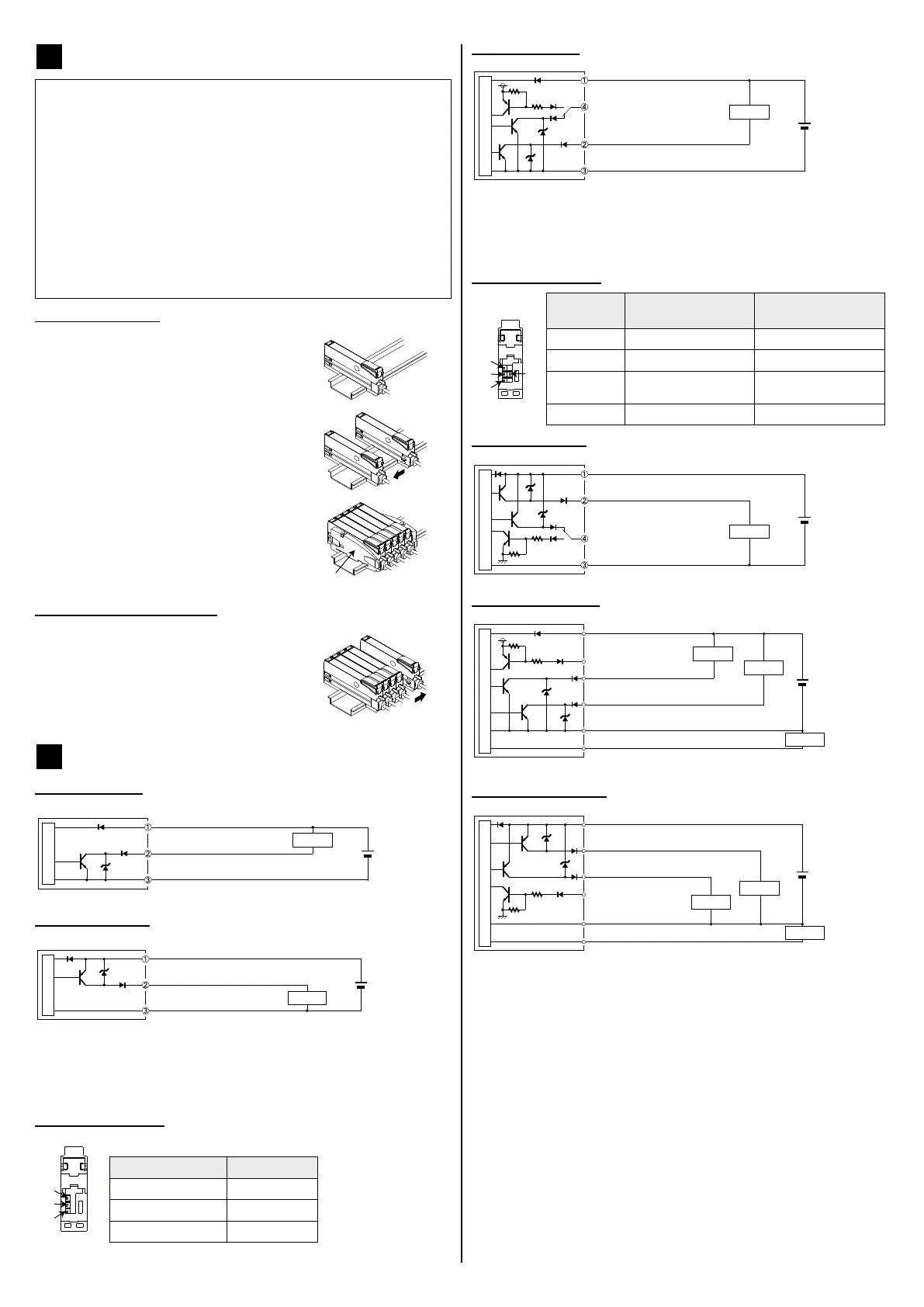
Cascading ampliers
1. Mount the ampliers one by one on the
DIN rail.
2. Slide the ampliers next to each other
and connect the quick‑connection cables
(main cable for the rst amplier, sub
cables for all ampliers after the rst).
3. Mount the end plates MS-DIN-E (1,
optional) at both ends of the cascade so
that their at sides hold the ampliers
together.
4. Tighten the screws to x the end plates.
1
Removing cascaded ampliers
1. Loosen the screws of the end plates.
2. Remove the end plates.
3. Slide the last amplier away from the oth‑
ers and remove them one by one.
5
I/O circuit diagrams
FX-501 (NPN type)
+
–
12–24V DC
(+10% / -15%)
Main circuit
Brown, +V (see note)
Load
Black, sensing output
Blue, 0V (see note)
FX-501P (PNP type)
12 to 24V DC
(+10% / -15%)
+
–
Main circuit
Brown, +V (see note)
Load
Black, sensing output
Blue, 0V (see note)
* The quick-connection sub cable does not have +V (brown)
and 0V (blue). The power is supplied from the connector of the
main cable.
Terminal arrangement
1
2
3
Terminal no. Function
1
+V
2
Sensing output
3
0V
FX-502 (NPN type)
+
–
12–24V DC
(+10% / -15%)
Main circuit
Brown, +V (see note)
Load
White, sensing output 2 /
external input
Blue, 0V (see note)
Black, sensing output 1
* The quick-connection sub cable does not have +V (brown)
and 0V (blue). The power is supplied from the connector of the
main cable.
Terminal arrangement
1
2
3
4
Terminal
no.
Function FX-501□ Function FX-502□
1
+V +V
2
Sensing output Sensing output 1
3
0V Sensing output 2/exter‑
nal input
4
── 0V
FX-502P (PNP type)
+
–
12–24V DC
(+10% / -15%)
Main circuit
Brown, +V (see note)
Load
Black, sensing output 1
Blue, 0V (see note)
White, sensing output 2 /
external input
FX-505-C2 (NPN type)
12–24V DC
(+10% / -15%)
(0–250Ω)
+
–
Main circuit
Brown, +V
Pink, external input
Load
Load
Load
White, sensing output 2
Blue, 0V
Gray, analog output (4–20mA)
Black, sensing output 1
FX-505P-C2 (PNP type)
12–24V DC
(+10% / -15%)
(0–250Ω)
+
–
Gray, analog output (4–20mA)
Main circuit
Brown, +V
Pink, external input
Load
Load
Load
White, sensing output 2
Blue, 0V
Black, sensing output 1
* Make sure to insulate the ends of all unused lead wires.
 Loading...