12
15
Interference prevention function
There are 2 options available for interference prevention:
● Interference prevention by optical communication (
, default).
● Interference prevention by different emitting frequency.
For the setting procedure, see “Pro5 menu items” on page 7.
Interference can be prevented only for a limited number of ampliers when
you have selected the default setting
(optical communication). The
number of ampliers depends on the response time you have selected, see
table below.
H-SP
≤25μs
FAST
≤60μs
STD
≤250μs
LONG
≤2ms
U-LG
≤4ms
HYPR
≤24ms
— 2 4 8 8 12
If you have mounted more ampliers than the interference prevention func‑
tion can cover, you need to prevent interference manually with one of the
two following methods:
● Attach the amplier protection seal FX-MB1 to the communication win‑
dow between the last amplier in the valid range and the rst amplier
of the next range (see example below).
● Turn the communication function OFF (
) for the amplier
after the valid range (see example below).
● If you have mounted more than the valid range of ampliers and the
ampliers use different response times, cover the communication
window between two ampliers with different response times with a
protection seal or turn the communication function OFF for the ampli‑
er in the master position.
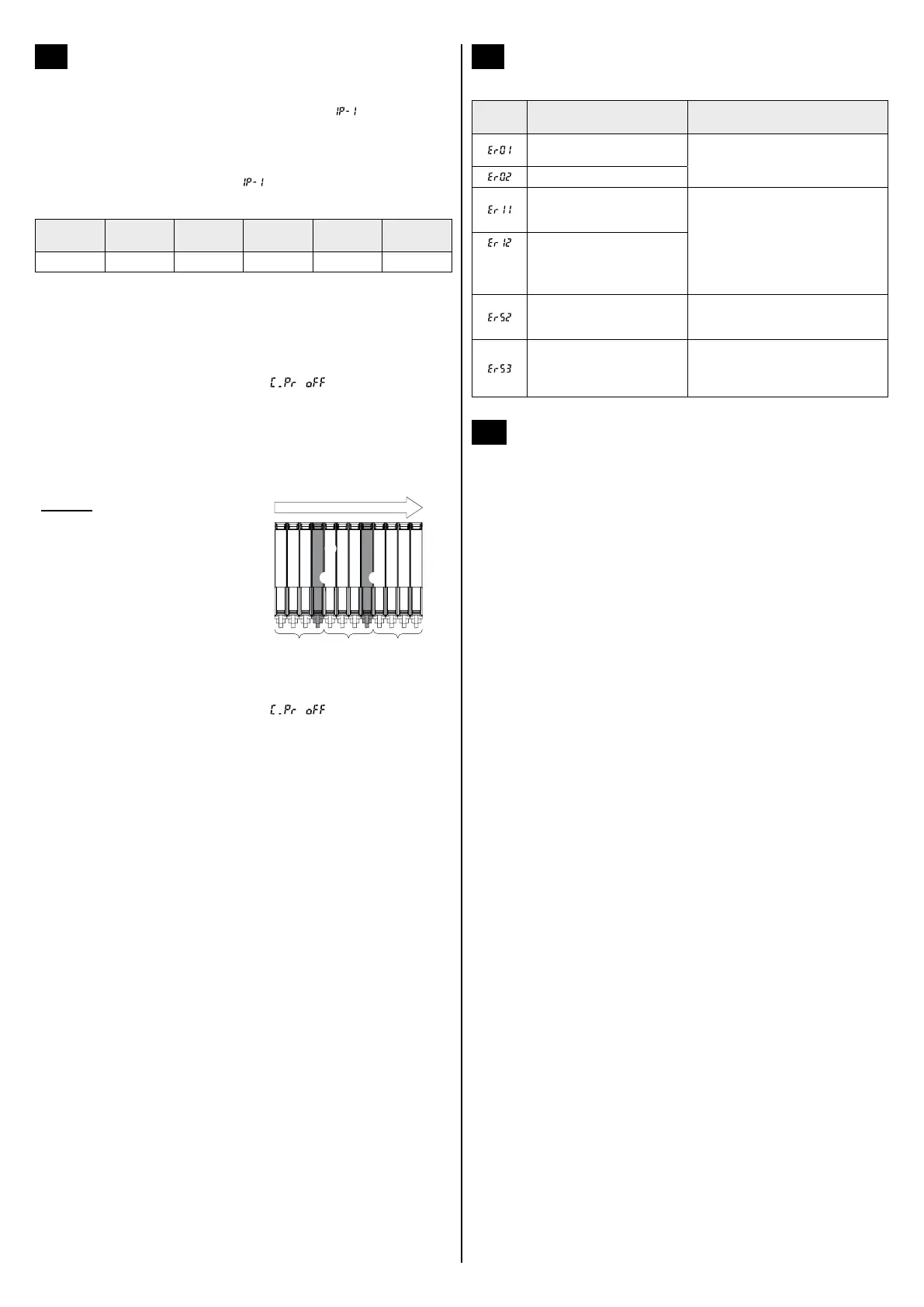
Example
You have mounted 12 ampliers
and the response time is STD. This
means, the valid range for the inter‑
ference prevention function is 4 ampli‑
ers (1). The last amplier in the
valid range is highlighted in gray.
To make sure that there is no interfer‑
ence between the 12 ampliers, use
one of the two following methods:
Communication direction
111
2
33
2
● Cover the communication window between the 4th and the 5th ampli‑
er (2) with the protection seal.
● Turn the communication function OFF (
) for the amplier
marked with 3 (for details, see “Pro4 menu items” on page 7).
16
Error codes and troubleshooting
The following error codes may appear in the digital display
Error
code
Description Remedy
EEPROM is broken or reached
the end of its working life.
Please contact our ofce.
Error writing on the EEPROM
Load of the sensing output 1
is short‑circuited causing an
over-current to ow.
Turn OFF the power and check the
load.
(only FX‑
502□)
Load of the sensing output 2
is short‑circuited causing an
over-current to ow.
Communication error when
the ampliers are mounted in
cascade.
Check that all ampliers are rmly
attached and that there is no gap
between ampliers.
Communication error between
the “master” communication
unit and the subordinated
ampliers.
Check that all ampliers are rmly
attached and that there is no gap be‑
tween the “master” communication unit
and the subordinated ampliers.
17
Cautions
● This product has been developed/produced for industrial use only.
● This product is suitable for indoor use only.
● Make sure to add or remove ampliers with the power OFF.
● If you apply a voltage exceeding the rated range or if an AC power
supply is connected directly, the product may get burnt or damaged.
● Shortcircuiting the load or wrong wiring may burn or damage the
product.
● Do not run the wires together with high‑voltage lines or power lines
or put them in the same raceway. This can cause malfunction due to
induction.
● Avoid using the product where there are strong magnetic elds as they
may prevent the product from working according to the specication.
● Verify that the supply voltage including the ripple is within the rating.
● If power is supplied from a commercial switching regulator, ensure that
the frame ground (F.G.) terminal of the power supply is connected to
an actual ground.
● In case noise generating equipment (switching regulator, inverter
motor, etc.) is used in the vicinity of this product, connect the frame
ground (F.G.) terminal of the equipment to an actual ground.
● Do not apply stress directly to the sensor cable joint or the ber cable
by forcibly bending or pulling.
● The ultra long response time settings U‑LG and HYPR are more likely
to be affected by extraneous noise since the sensitivity is higher than
with other response times. Test the behavior of the product before use.
● Do not use during the initial transient time (H‑SP, FAST, STD: 0.5
seconds, LONG, U‑LG, HYPR: 1 second) after the power supply is
switched ON.
● Use the quick-connection cable (see Specications on page 13).
You can extend the cable up to 100m max. with 0.3mm
2
or more
cable. However, in order to reduce noise, make the wiring as short as
possible.
● Do not use the product in dusty or dirty places or in places that are
exposed to steam.
● Protect the sensor from water, oil, grease, organic solvents such as
thinner, etc., strong acid, and alkaline.
● This product cannot be used in an environment containing inam‑
mable or explosive gasses.
● Never disassemble or modify the product.
● This product uses an EEPROM. Due to the EEPROM’s lifetime, do not
expect to make settings more than 100 thousand times.

 Loading...