11
Red digital display
Code
Forth digit
Code
Third digit
Code
Second
digit
Code
First digit
Copy lock
setting
Hys‑
teresis
setting
Setting items
in the digital
display
Backup
setting
Response
time set‑
ting
Sensing
output
setting (see
note)
Copy lock
OFF
H‑02
Incident light
intensity
Backup
ON
H‑SP
Normal
mode
Copy lock
ON
H‑02
Incident light
intensity
Backup
OFF
FAST WC
Copy lock
OFF
H‑03
Displayed as
a percentage
Backup
ON
STD
Rising
differential
mode
Copy lock
ON
H‑03
Displayed as
a percentage
Backup
OFF
LONG
Falling
differential
mode
Copy lock
OFF
H‑01
Peak / bottom
value
Backup
ON
U‑LG HYS
Copy lock
ON
H‑01
Peak / bottom
value
Backup
OFF
HYPR –
* Note that you can only make settings for sensing output 1.
Sensing output 2 cannot be set.
FX-505□-C2
Green digital display
Code
Forth digit
Code
Third digit
Code
Second
digit
Code
First digit
Sensing output
operation mode
Timer operation
Time
delay
CUSTOM
setting
Sensing
output 1
Sensing
output 2
Sensing
output 1
Sensing
output 2
Light‑ON Light‑ON No timer No timer 0.5ms
Response
time setting
Light‑ON Dark‑ON OFD No timer 1ms
Emission
power setting
Dark‑ON Light‑ON OND No timer 3ms
Hysteresis
setting
Dark‑ON Dark‑ON ONOF No timer 5ms –
– – OSD No timer 10ms –
– – ONOS No timer 30ms –
– – No timer OFD 50ms –
– – No timer OND 100ms –
– – No timer OSD 300ms –
– – – – 500ms –
– – – – 1s –
– – – – 2s –
– – – – 3s –
– – – – 4s –
– – – – 5s –
Red digital display
Code
Forth digit
Code
Third digit
Code
Second
digit
Code
First digit
Copy
lock
setting
Hys‑
teresis
setting
Setting items
in the digital
display
Backup
setting
Re‑
sponse
time
setting
Sensing output
setting
Sensing
output 1
Sensing
output 2
Copy
lock
OFF
H‑02
Incident light
intensity
Backup
ON
H‑SP
Normal
mode
Normal
mode
Copy
lock ON
H‑02
Incident light
intensity
Backup
OFF
FAST
Normal
mode
Rising
differ‑
ential
mode
Copy
lock
OFF
H‑03
Displayed as
a percent‑
age
Backup
ON
STD
Normal
mode
Falling
differ‑
ential
mode
Copy
lock ON
H‑03
Displayed as
a percent‑
age
Backup
OFF
LONG
Normal
mode
HYS
Copy
lock
OFF
H‑01
Peak / bot‑
tom value
Backup
ON
U‑LG
Normal
mode
Self‑di‑
agnosis
output
mode
Copy
lock ON
H‑01
Peak / bot‑
tom value
Backup
OFF
HYPR
Normal
mode
Answer
back
mode
– – – – – WC
Normal
mode
‑ ‑ ‑ ‑ ‑ WC HYS
‑ ‑ ‑ ‑ ‑
Rising
differ‑
ential
mode
Falling
differ‑
ential
mode
‑ ‑ ‑ ‑ ‑ HYS
Normal
mode
14
Optical communication
It is possible to use optical communication for the following functions.
● Data bank loading/saving (use FX-502□ or FX-505□-C2 as the main
amplier)
● Copy settings
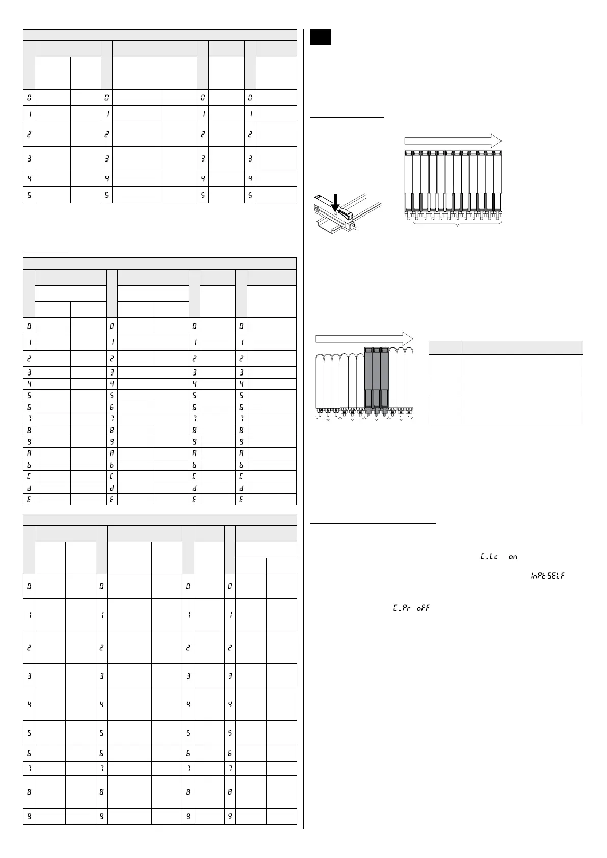
Notes on mounting
Communication
is performed via
the communica‑
tion window of the
amplier (marked
with an arrow).
Communication direction
1
2
For optical com‑
munication to
work, you need to
cascade the sub
ampliers (2) to
the right of the
main amplier
(1).
● Make sure to mount the ampliers closely when the interference pre‑
vention function is controlled by optical communication (default setting,
refer to “Pro5 menu items” on page 7).
● When you cascade this product together with other products (e.g. ber
sensor ampliers, pressure sensor controllers, etc.), install the prod‑
ucts so that they are in order of group A, B, D and C as shown in the
gure below. This product is included in group D. Within each group,
identical models should be mounted next to each other.
Communication direction
Group
A
Group
B
Group
D
Group
C
Group Model number
A
FX-301□ (conventional version unit)
FX-301B□/G□/H□, LS-401□
B
FX-301□ (modied version unit)
FX-305□, FX-301□-C1
C LS-403□, DPS series
D FX-500 series
● If products of different groups are mounted together, cover the com‑
munication window on the products at both ends of each group with
the amplier protection seal FX-MB1 (optional).
● If you use copy setting for a cascade of different products from the FX‑
500 series, each product will only accept the settings that it supports
and ignore settings for unsupported functions.
Notes on optical communication
● Optical communication is not possible if an amplier is in one of the
following states:
‑ The copy lock has been activated (setting
).
‑ The digital display is blinking.
‑ The external input setting of the main amplier is set to
(only for databank loading/saving).
● When the communication protocol of a sub amplier is set to halt com‑
munication (setting
), it is not possible to communicate with
any of the sub ampliers mounted to the right of said sub amplier.
 Loading...