43
9.1.3. Disassembly Procedure
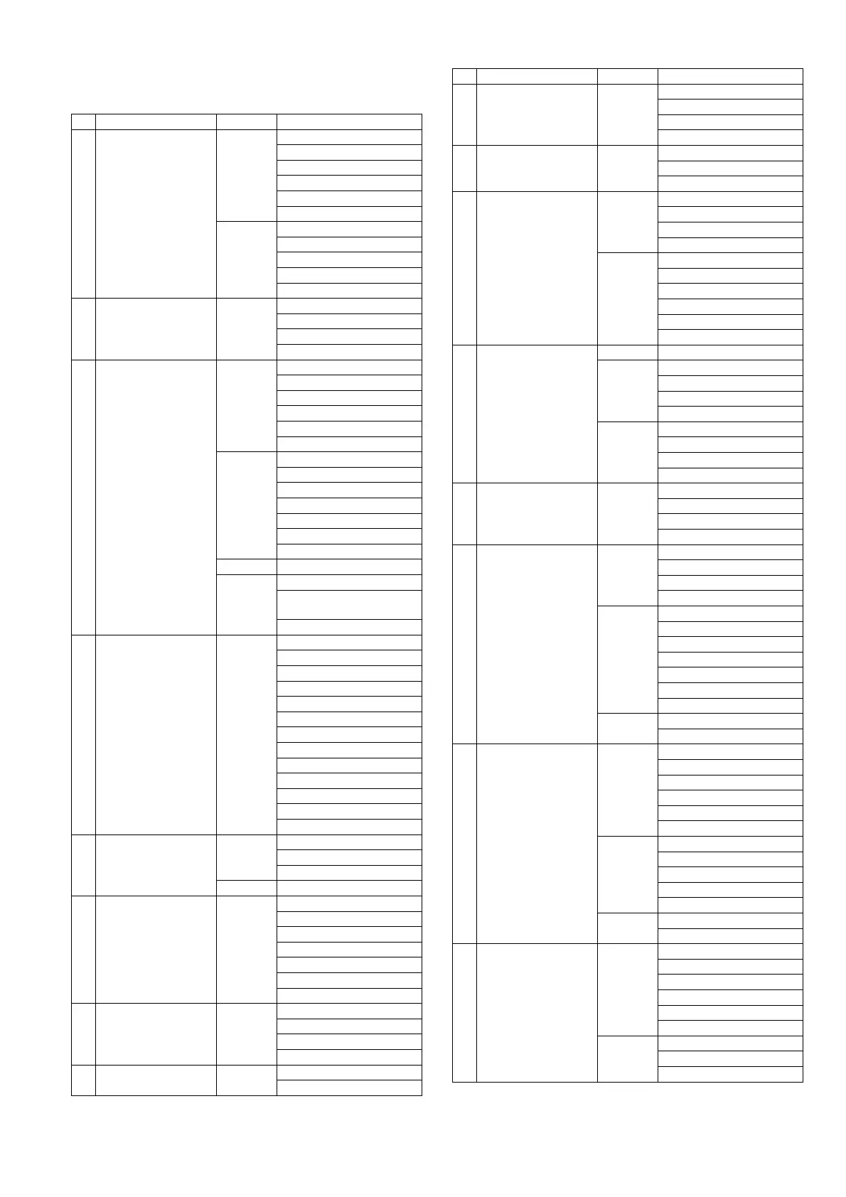
No. Item Fig. Removal
1 Rear Case Unit (Fig. D1) Memory Card
Battery
Screw (A) x 1
Screw (B) x 1
Screw (C) x 4
Screw (D) x 1
(Fig. D2) Screw (E) x 2
Screw (F) x 1
FP9005 (Flex)
FP9301 (Flex)
Rear Case Unit
2 Rear Operation Unit (Fig. D3) Screw (G) x 3
Screw (H) x 2
Convex x 3
Rear Operation Unit
3 Top Case Unit
Flash P.C.B.
(Fig. D4) Hot Shoe Cover
Shoe Spring
Screw (I) x 1
FP9009 (Flex)
FP9013 (Flex)
FP9401 (Flex)
(Fig. D5) Screw (J) x 1
Screw (K) x 1
Battery PCB Cover
FP8201 (Flex)
P8203 (Connector)
Convex x 1
Top Case Unit
(Fig. D6) (Discharge the E.Capacitor)
(Fig. D7) P8202 (Connector)
Solder
(2 points / component side)
Flash P.C.B.
4 Main P.C.B. (Fig. D8) FP9001 (Flex)
FP9003 (Flex)
FP9004 (Flex)
FP9006 (Flex)
FP9007 (Flex)
FP9010 (Flex)
FP9011 (Flex)
FP9012 (Flex)
P9001(Connector)
Screw (L) x 4
FP3901 (Flex)
FP3902 (Flex)
Main P.C.B.
5 Mount Box Unit (Fig. D9) Screw (M) x 2
Tripod Plate
Screw (N) x 4
(Fig. D10) Mount Box Unit
6 Jack Door
Speaker
(Fig. D11) Screw (O) x 2
Jack Door
Screw (P) x 1
Convex x 4
Side Plate R
Jack Holder
Speaker
7 Battery Unit (Fig. D12) Screw (Q) x 3
Screw (R) x 1
Convex x 1
Battery Unit
8 Flash Sub P.C.B. Unit (Fig. D13) Screw (S) x 1
Flash Sub P.C.B. Unit
9 Wi-Fi P.C.B. (Fig. D14) Screw (T) x 1
Convex x 1
Hooking part x 1
Wi-Fi P.C.B.
10 Battery Door Unit (Fig. D15) Battery Door Shaft
Battery Door Spring
Battery Door Unit
11 NFC Antenna Unit
SD P.C.B.
(Fig. D16) FP8002 (Flex)
Locking tab x 1
Hooking part x 1
NFC Antenna Unit
(Fig. D17) Screw (U) x 1
Screw (V) x 1
Convex x 2
PCB Gnd Plate
Convex x 2
SD P.C.B.
12 Battery Case
Battery Out Spring
(Fig. D18) Screw (W) x 2
(Fig. D19) PCB Spacer Plate
Convex x 2
Battery Frame Bottom
Convex x 2
(Fig. D20) Battery Case
Battery Frame Top
Hooking part x 1
Battery Out Spring
13 Rear Dial Unit (Fig. D21) Screw (X) x 2
Convex x 2
Connector (A)
Rear Dial Unit
14 Flash Unit (Fig. D22) Screw (Y) x 1
Locking tab x 2
Convex x 1
Flash Lock Plate
(Fig. D23) Flash Lock Spring
Flash Lock Lever
Screw (Z) x 3
Screw (a) x 1
Convex x 2
Hooking part x 1
Screw (b) x 1
(Fig. D24) Convex x 2
Flash Unit
15 Flash (Fig. D25) Flash Shaft
Hooking part x 2
Flash Spring
Flash Base
Locking tab x 4
Flash Arm Cover
(Fig. D26) Screw (c) x 1
Locking tab x 2
Hooking part x 2
Flash Case Top
Flash
(Fig. D27) Screw (d) x 2
Flash Arm
16 LVF Unit (Fig. D28) Screw (e) x 1
Convex x 2
Hooking part x 1
LVF Blind Plate
Convex x 2
FPC Tape
(Fig. D29) Screw (f) x 2
Convex x 2
LVF Unit
No. Item Fig. Removal

 Loading...