-
31
--
30
-
Assembling of gear head
Assembling of gear head
• Preparation for assembling
[1]
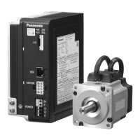
Gear head applicable to the motor described in this instruction manual is MB8G
□
BV
(for 50W) and MB9G
□
BV (for 90 W and 130 W). Never use a combination of gear
heads other than applicable ones.
Failure to observe this instruction will result in
malfunction.
[2] Make sure that O-ring is attached to the bottom of spigot joint.
When the gear head is assembled with O-ring oating, it may result in grease leakage.
[3] When grease adheres to the end surface of gear head, wipe off clean.
If the gear head is assembled with grease adhered, it may cause grease to exude.
• Assembling
[1] Direct the motor pinion upward, and make sure that the relation between direction of
motor lead wire and output shaft matches with the equipment.
[2] Turn the motor pinion nely clockwise and counterclockwise for assembling, ensuring
that the tip of motor pinion does not hit the tooth of gear head.
<Information>
MB type gear head is provided with temporary assembling screw (two hexagon sock-
et head bolt). Before installing the equipment, assemble the motor and gear head
temporarily, which will ensure stable installation of the equipment. In installing to the
equipment, be sure to use four “mounting screws” attached to the gear head for se-
cure installation.
[Recommended tightening torque for temporary assembling]
Size
Gear head
type
Screw
size
Tightening
torque
Screw
length
80 mm sq.
MB8G M2.6 0.5 N
・
m
12 mm
90 mm sq.
MB9G M3 0.8 N
・
m
Temporary
assembling
screw
[3] When installing the motor and gear head to the mating equipment, use “mounting
screws” attached to the gear head, tighten them sufciently to eliminate clearance
between the motor ange surface and gear head spigot joint while paying attention to
bite of O-ring.
Recommended tightening torque is shown below:
Size
Gear head
type
Screw
size
Tightening
torque
Attachment
pitch
80 mm sq.
MB8G M6 2.9 N
・
m
94 mm
90 mm sq.
MB9G M8 7.8 N
・
m
104 mm
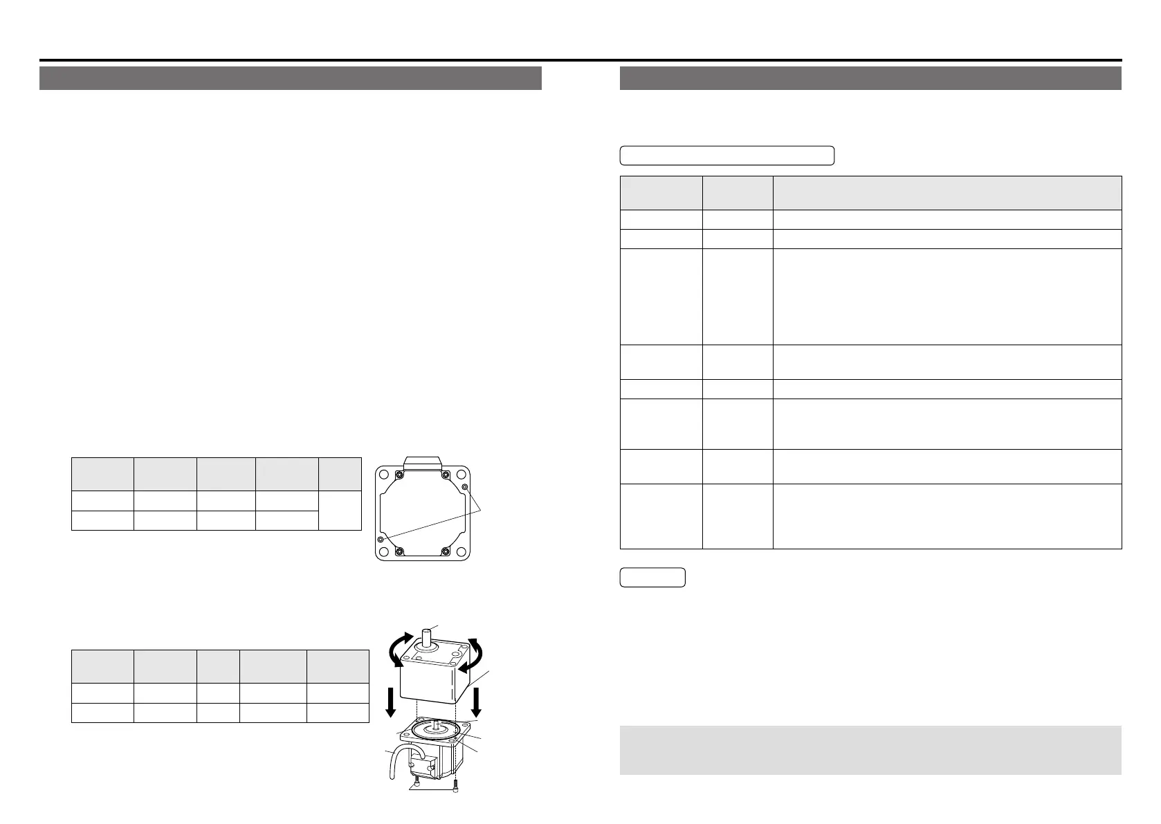
• Assemble with motor pinion faced up.
• Outward direction of motor leadwire can be
aligned with any one of 4 sides of gear head
with an output shaft at a different position.
Faucet
portion
end face
Faucet face
O-ring
Motor pinion
Leadwires
Flange face
Temporary
assembling screw
Maintenance/ Inspections
Maintenance/ Inspections
Routine maintenance and inspection are essential for proper and satisfactory operation of
the motor.
Maintenance/ Inspection item
Maintenance/
Check item
Inspection
procedure
Condition
Input voltage Voltmeter Must be within ±10% of rating.
Input current Ammeter Must be within rated input current described on nameplate.
Insulation
resistance
Insulation
resistance
tester
The resistance of motor should be 1 MΩ or higher when tested
with a 500 V megger.
Measuring position:
Between power input line (L1, L2,L3) and grounding wire
Brushless motor:
Across phase (U, V, W) and ground terminals
Noise Hearing
Noise level must not be different from the usual level. In addition,
abnormal noise such as rumbling noise must not be heard.
Vibration By hand Free from abnormal vibration.
Grease
leakage
Visual check
Check that circumference of the motor and gear head are free
from oil and grease.
If grease leakage will cause problem, use grease sealing cover.
Installation
bolt
Torque
wrench
Check for loosening of bolt, and tighten additionally as
necessary.
Use
environment
By sight
Check the ambient temperature and humidity, and make sure
that dirt, dust, or foreign substance is not found.
Check the waste thread etc don’t attached to the windhole of
brushless amplier.
Caution
• Power-on/off operations should be done by the operators themselves for ensuring safety
in checking.
• Do not touch the motor while it is running or immediately after it stops because it gets hot
and stays hot for a while after power has been turned off.
• When testing the insulation resistance of the brushless amplier with the megger, discon-
nect the amplier from all associated devices. Performing megger testing without rst
disconnecting these devices will cause failure.
When disassembly, troubleshooting, etc., is needed,
be sure to contact our service department or the sales agent of purchase.
 Loading...