-
13
--
12
-
Digital key pad connecting cable
(option)
Connector
for SER.
It cannot be used
simultaneously.
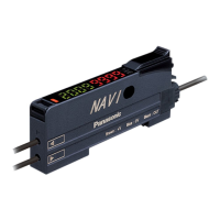
Digital key pad
(option)
Digital display console.
It enables change of
parameter.
(refer to P.18)
RS485
Communication software
PANATERM for BL
Please download from our web site
Change of parameter seting
monitor of a control state
Motor extension cable
(option)
Select if needed (to 10 m).
Power supply connection
connector kit
(option)
Personal computer
(Customer preparation)
Gear head
(option)
PC connecting cable (option)
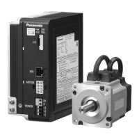
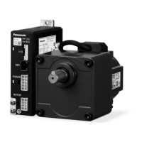
GP series
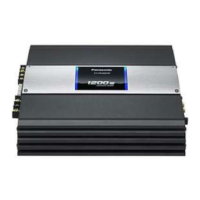
Brushless motor
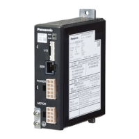
GP series
Brushless amplifier
Noise
filter
Magnetic
contactor
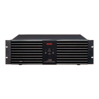
External
regenerative
resistor
(Option)
MCCB
POWER
It cannot be used
simultaneously.
AC power supply
If your PC does not have RS232 port,
use RS232-USB converter.
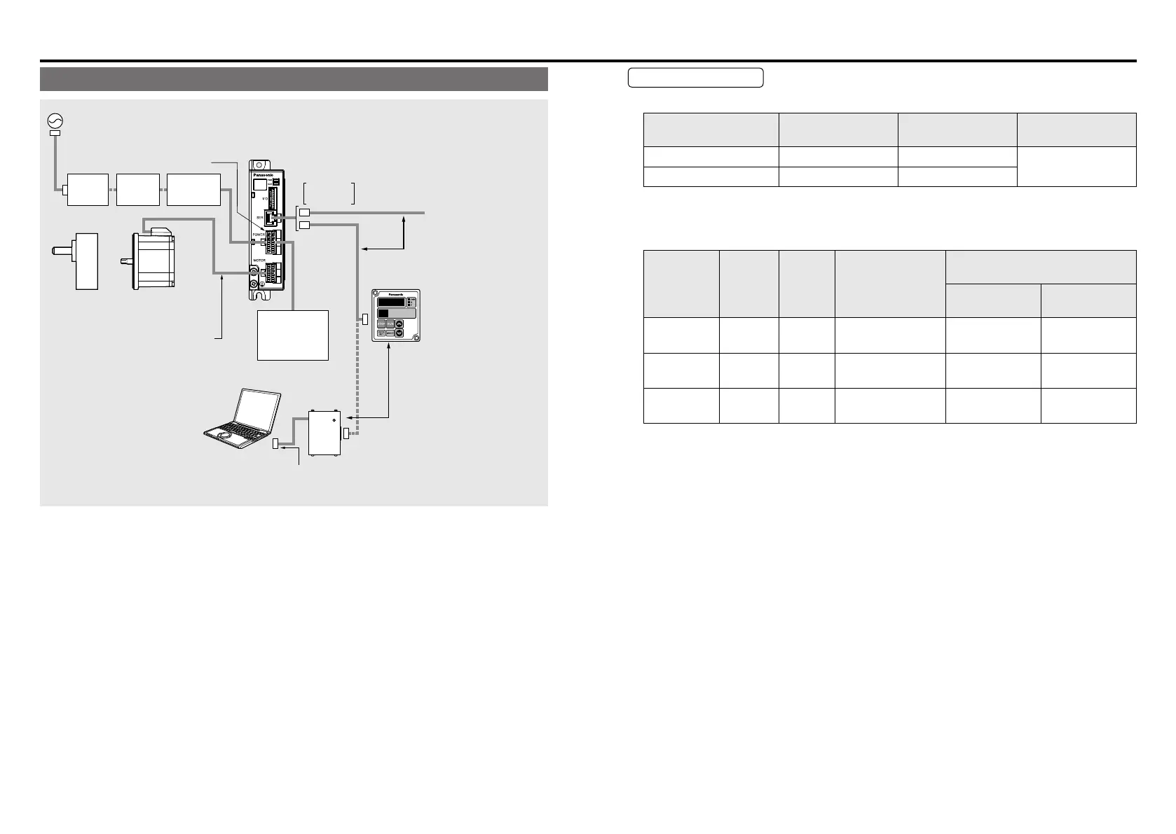
System conguration and wiring System conguration and wiring
System conguration/ general wiring diagram
• Wiring work shall be performed by qualied electric engineering technician.
• Do not turn on power before nishing wiring, to avoid risk of electric shock.
• For details of options (sold separately), see P.102.
Wiring equipment
• Recommended noise lter
Voltage
Optional part
number (option)
Manufacturer's
part No.
Manufacturer
Single phase 100, 200 V DV0P4170 SUP-EK5-ER-6
OKAYA ELECTRIC
IND. CO., LTD.
3-phase DV0PM20042 3SUP-HU10-ER-6
• Selection of Molded Case Circuit Breaker (MCCB), magnetic contactor, and electric wire
(wiring within equipment) (refer to P.91 “Conformance to EC directive and UL standard”
for compatibility with overseas standard.)
Voltage
Capacity
(W)
MCCB
rated
(
current
)
Magnetic
contactor rated
current
(contact structure)
Electric wire (mm
2
)
(Wiring within equipment)
Main circuit/
Grounding wire
Control circuit
Single phase
100V
50 to 130 5 A 20 A (3P+1a) 0.5 (AWG20) 0.13 (AWG26)
Single phase
200V
50 to 130 5 A 20 A (3P+1a) 0.5 (AWG20) 0.13 (AWG26)
3-phase
200V
50 to 130 5 A 20 A (3P+1a) 0.5 (AWG20) 0.13 (AWG26)
■
Be sure to ground the grounding terminal.
In wiring to power supply (outside of equipment) from MCCB, use an electric wire of 1.6
mm
diameter (2.0 mm
2
) or more both for main circuit and grounding. Apply grounding
class D (100 Ω or below) for grounding. Do not tighten the ground wires together, please
tighten them individually.
•
Selection of relay
As for use for control circuit such as control input terminal, use a relay for small signal
(minimum guarantee current 1 mA or less) for preventing poor contact.
<Reference example>
Panasonic: DS type, NK type, HC type, OMRON: G2A type
•
Control Circuit Switch
When using a switch instead of relay, use one for minute current in order to prevent poor
contact.
<Example>
Nihon Kaiheiki Ind.Co.,Ltd: M-2012J-G
 Loading...