21
English
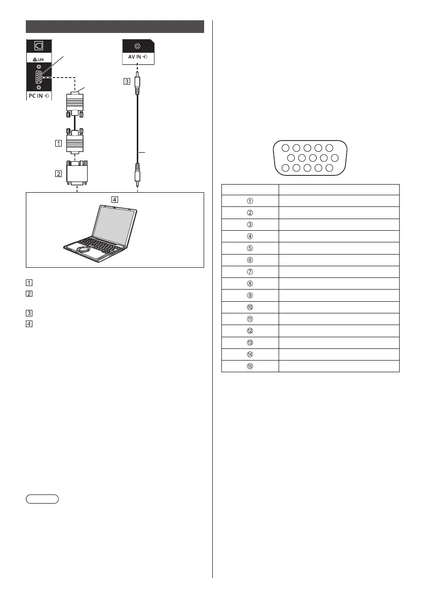
PC IN terminal connection
DIGITAL LINK
Connect a cable
which matches
the audio output
terminal on the
computer.
(commercially
available)
(Female)
(Male)
Mini D-sub 15p cable (commercially available)
Conversion adapter (if necessary) (commercially
available)
Stereo mini plug (M3) cable (commercially available)
PC
The type of computer signal that can be connected
●
With regard to the typical PC input signals that
are described in “Preset Signals” (see page 117),
adjustment values such as for the standard picture
positions and sizes have already been stored in this
unit.
(Computer signals which can be input are those with
a horizontal scanning frequency of 30 to 110 kHz and
vertical scanning frequency of 48 to 120 Hz.)
●
The display resolution is a maximum of 1 440 x 1 080
dots when the aspect mode is set to [4:3], and 1 920
x 1 080 dots when the aspect mode is set to [16:9].
If the display resolution exceeds these maximums, it
may not be possible to show fine detail with sufficient
clarity.
●
In [ENGLISH(US)] OSD language, [16:9] is displayed
as [FULL].
Note
●
The PC IN terminal is DDC2B-compatible. If the
computer being connected is not DDC2B-compatible,
you will need to make setting changes to the
computer at the time of connection.
●
There is no need to use an adapter for computers
with DOS/V compatible Mini D-sub 15P terminal.
●
Additional computer, cables and conversion adapter
shown are not supplied with this set.
●
Do not set the horizontal and vertical scanning
frequencies for PC signals which are above or below
the specified frequency range.
●
Component Input is possible with the pin 1, 2, 3 of the
Mini D-sub 15P Connector.
●
Change the [Component/RGB-in select] setting in
the [Signal] menu to [Component] (when Component
signal connection) or [RGB] (when RGB signal
connection). (see page 48)
●
Audio input is shared with AV IN terminal.
Pin assignments and signal names for PC Input
Terminal (Mini D-sub 15P)
1
678
3
9
45
10
15 14 13 12 11
2
Pin No. Signal Name
R (PR/CR)
G (Y)
B (PB/CB)
NC (not connected)
GND (Ground)
GND (Ground)
GND (Ground)
GND (Ground)
+5 V DC
GND (Ground)
NC (not connected)
SDA
HD/SYNC
VD
SCL

 Loading...