Page 5
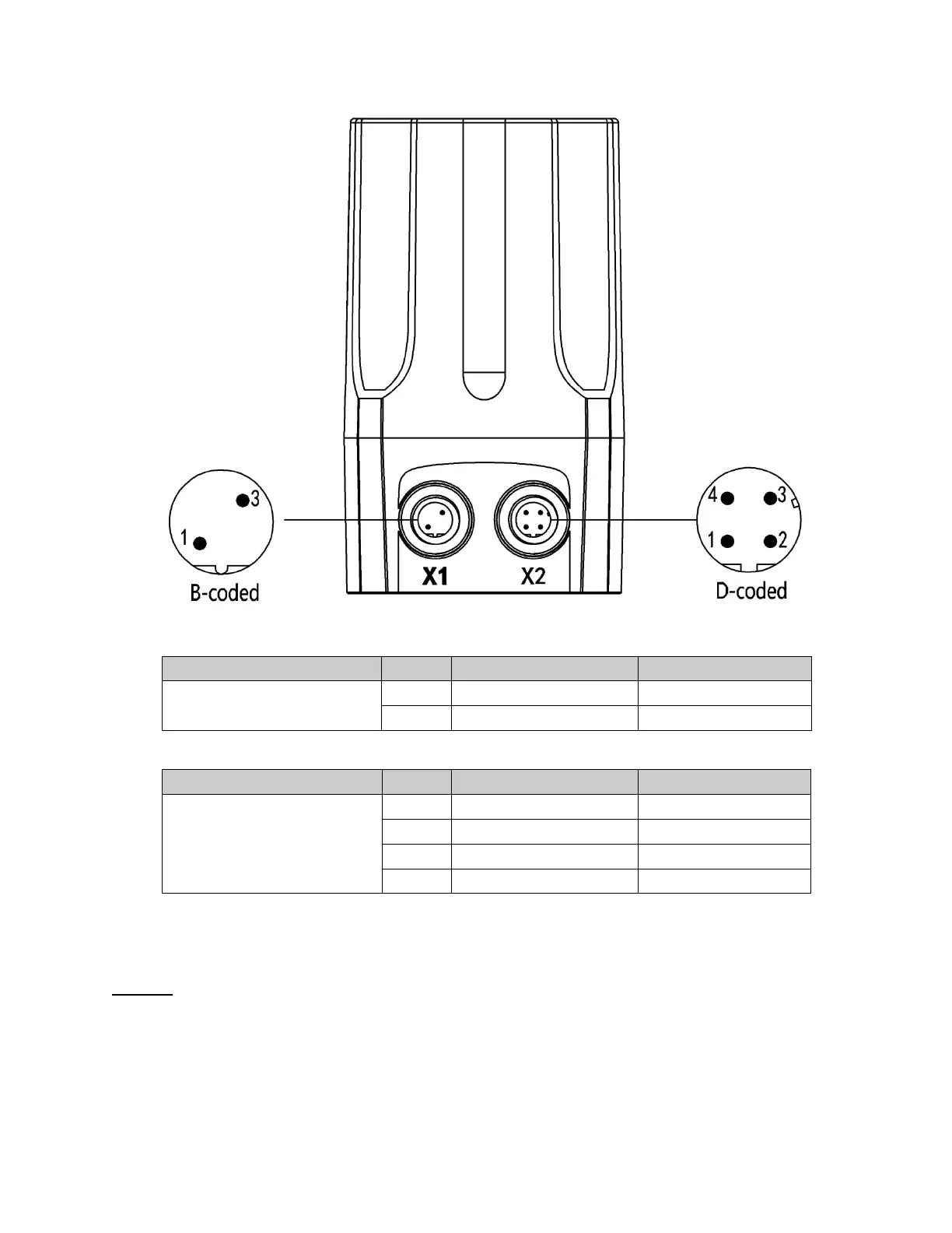
Electrical Connections
Figure 2. Connection
1
Analog signal output + 0/4 – 20 mA
3
Analog signal output GND GND
Table 1. Electrical connection description – X1
X2
1
Power supply + +24 V
2
Power supply GND GND
3
Set signal input + 0/4 – 20 mA
Set signal input GND GND
Table 2. Electrical connection description – X2
CAUTION: Improper wiring to the electrical connectors may cause damage to the positioner electronics.
 Loading...