Page 6
Pneumatic Connections
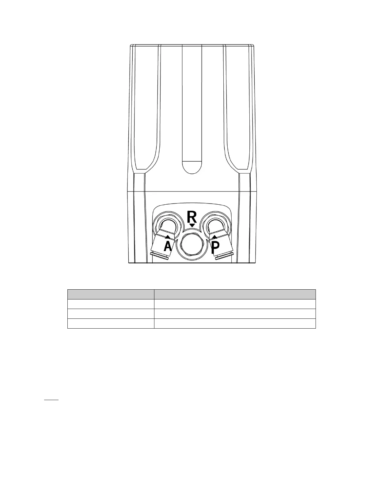
Figure 3. Pneumatic connections
Pilot air supply (built-in filter, filter size 5 micron)
Pilot air exhaust
Actuator air connection
Table 3. Pneumatic connections
DIGITAL POSITIONER Connections
Connect the pilot air supply to the “P” port on the positioner (Fig 3). Pilot air supply pressure greater than 101.5 psi (7 bar) may
damage the positioner. The pilot air supply must be non-lubricated, dry industrial air filtered to 40 microns.
NOTE: Pilot supply air must be instrument quality, free of water and oils.
The electrical connection of the set point signal should be carried through a shielded cable. The external supply voltage should
be connected via a separate cable.
Cable bushings not used should be sealed using a suitable sealing cap to preserve the protection class (IP66).
 Loading...