1 9
NI CYIEGB
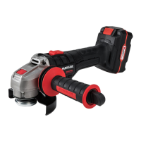
Checking the battery charge
level
The battery’s ( 9) charge level is indi-
cated by the charge state indicator (
6).
The LEDs indicate the battery’s charge
level, when the device is in operation.
Press and hold the power button (
5).
red-yellow-green => Battery fully charged
red and yellow => Battery half charged
red => Battery needs
to be charged
Assembly
Caution! Risk of injury!
- Ensure that you have sufcient
space in which to work, and that
you do not endanger other people.
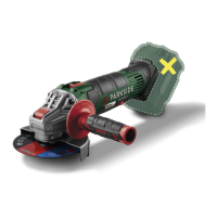
Set protective hood
Adjust the protective hood such that any
sparks or detached parts cannot hit either
the user or any bystanders.
The protective hood must also be positi-
oned such that the sparks cannot ignite
combustible parts, including those in the
surroundings.
The device must only be
operated with the protective
hood mounted.
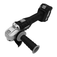
1. Remove the battery (9). Press the
battery release buttons (8) and
pull the battery (9) out of the
tool.
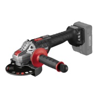
2. Turn the protective hood (1) into
the working position. The closed
side of the protective hood must
always face the operator.
Installing/changing the
cutting/grinding disc
Before initial operation,
check the tightness of the
clamping screw (3).
1. Press the spindle retaining tab
(4) and keep it pressed.
2. Loosen the clamping screw (3)
with the Allen key (11). You can
now release the spindle retaining
tab (4).
3. Position the desired cutting/
grinding disc (2) on the moun-
ting ange (
16). The label on
the cutting/grinding disc should
always face the tool.
4. Reposition the clamping ange
(17). The side of the clamping
ange (
17). The side of the
clamping ange (
17) with re-
cess generally points to the attach-
ment tool and thus to the cutting/
grinding disc (2).
5. Press the spindle retaining tab (4)
and tighten the clamping screw (3)
using the Allen key (11). You can
now release the spindle retaining
tab (4).
If the direction of rotation is marked
on your cutting/grinding disc, make
sure that it matches the direction of
rotation mark on the tool.
 Loading...