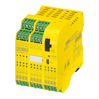
4.2. Adaptación CTS/RTS
Si es necesario se pueden puentear las
líneas de mando CTS/RTS por medio de
un campo Jumper X7 (configuración de
suministro, fig. 12 a) o, a opción, colocar
activo a lógico 1 (fig. 13 b, ejemplo:
RTS = lógico 1).
• Las líneas de mando DSR/DTR están
puenteadas internamente en fijo.
Condición: dichas líneas están cablea-
das en el cable RS-232 (fig. 8).
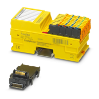
5. El interface TTY
5.1. Conexión de conductores
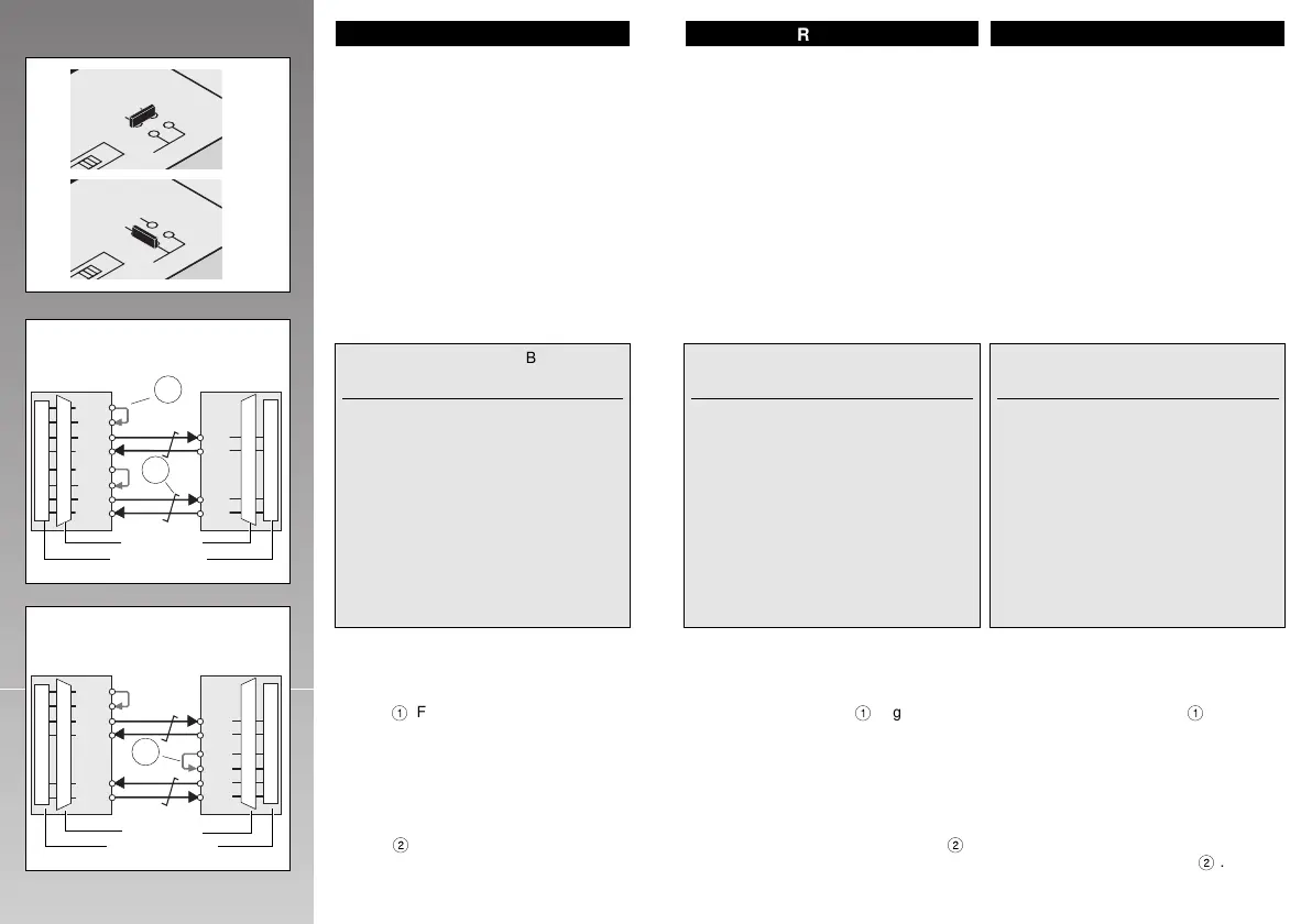
5.2. Tipos de servicio
El tipo de servicio deseado activo,
semiactivo o pasivo se ajusta mediante
puenteado de cable externo
1
(figuras
14/15) y se determina mediante la
construcción del cableado.
Solo puede conectarse un interface activo
con otro pasivo o dos semiactivos mutua-
mente.
Como cable de conexión se recomienda
utilizar cable blindado de par trenzado
(2 x 2 conductores trenzados,
2
).
18 19
X7
4 3
CTS
RTS
2 1 +
Fig.13 b
X7
4 3
CTS
RTS
2 1 +
Fig.13 a
(S1+)
(T +)
(T –)
(S1–)
(R +)
(R –)
R +
R –
S1+
T +
T –
S1–
3
2
6
7
4
8
4
8
7
3
6
5
3
2
6
7
4
8
6
5
4
8
7
3
Fig.14
S1+
T +
T –
S1–
S2+
R +
R –
S2–
R+
R–
T+
T–
4
8
2
6
6
5
8
7
3
2
6
7
5
4
8
9
4
8
7
3
2
6
5
1
PSM-EG-TTY PSM-EG-TTY
active passive
actif passif
activo pasivo
PSM-EG-TTY PSM-EG-TTY
semi active semi active
Semi-actif Semi-actif
semiactivo semiactivo
Fig.15
SUB-D 9
SUB-D 9
ESPAÑOL
COMBICON /
MINICONNEC
COMBICON /
MINICONNEC
ENGLISH
4.2. CTS/RTS Support
The control wires CTS/RTS can be
jumpered on the jumper field X7 (default
configuration, Fig.12a) or as an option,
actively set to logical '1' (Fig. 13b,
example: RTS = logical '1').
• The control lines DSR/DTR are perma-
nently bridged internally!
Prerequisite: In the RS-232 cable, these
lines must be wired as well (Fig. 8)!
5. The TTY Interface
5.1. Pin Assignments
5.2. Operating Modes
The desired operating mode active, semi
active or passive is set via external cable
bridges
1
(Fig. 14/15) and determined by
the wiring design.
Only one fully active interface and one
passive interface or two semi active inter-
faces may be connected with each other!
For connection cables, we recommend
shielded twisted pair cables (2 x 2 wires
twisted,
2
).
FRANÇAIS
4.2. Adaptation CTS/RTS
Si nécessaire, vous pouvez ponter les
lignes de commande CTS/RTS par le biais
du tableau de cavaliers X7 (configuration
d'usine, fig.12a) ou, au choix, les position-
ner de façon active sur logique 1
(Fig.13b, exemple: RTS = logique 1).
• Les lignes de commande DSR/DTR
font l'objet d'un pontage interne fixe !
Pour cela, ces lignes doivent être
câblées dans le câble RS-232 (Fig.8)!
5. Interface TTY
5.1. Plan des raccordements
5.2. Modes de fonctionnement
Le mode de fonctionnement souhaité: actif,
semi-actif ou passif, s'obtient par le biais
de câbles-ponts externe
1
(Fig. 14/15) et
de la structure du câblage.
On ne doit raccorder qu'une seule inter-
face active à une passive ou à deux semi-
actives !
Comme câble de liaison, nous recomman-
dons des câbles à paires torsadées proté-
gé par un blindage (2 x 2 fils torsadés
2
).
COMBI- SUB-D
Description CON 9-pos.
(from right) (female)
Current source 2
neg. polarity S1- Pin 3 Pin 7
pos. polarity S1+ Pin 4 Pin 3
Current source 1
neg. polarity S2- Pin 1 Pin 9
pos. polarity S2+ Pin 2 Pin 5
Transmit data
neg. polarity T- Pin 7 Pin 6
pos. polarity T+ Pin 8 Pin 2
Receive data
neg. polarity R- Pin 5 Pin 8
pos. polarity R+ Pin 6 Pin 4
Ground
6 –– Shield
MINI- SUB-D
Désignation CONNEC 9 pôles
(de D. à G.) (femelle)
Source tension 2
polarité négative S1- Pin 3 Pin 7
polarité positive S1+ Pin 4 Pin 3
Source tension 1
polarité négative S2- Pin 1 Pin 9
polarité positive S2+ Pin 2 Pin 5
Emission
polarité négative T- Pin 7 Pin 6
polarité positive T+ Pin 8 Pin 2
Réception
polarité négative R- Pin 5 Pin 8
polarité positive R+ Pin 6 Pin 4
Connexion terre
6 –– Blind.
COMBI- SUB-D
Denominación CON 9 polos
(de la dr.) (hembra)
Fuente 2
polaridad negativa S1- Pin 3 Pin 7
polaridad positiva S1+ Pin 4 Pin 3
Fuente 1
polaridad negativa S2- Pin 1 Pin 9
polaridad positiva S2+ Pin 2 Pin 5
Datos emisión
polaridad negativa T- Pin 7 Pin 6
polaridad positiva T+ Pin 8 Pin 2
Datos recepción
polaridad negativa R- Pin 5 Pin 8
polaridad positiva R+ Pin 6 Pin 4
conexión a tierra
6 –– Malla

 Loading...