2. Anschlußhinweise
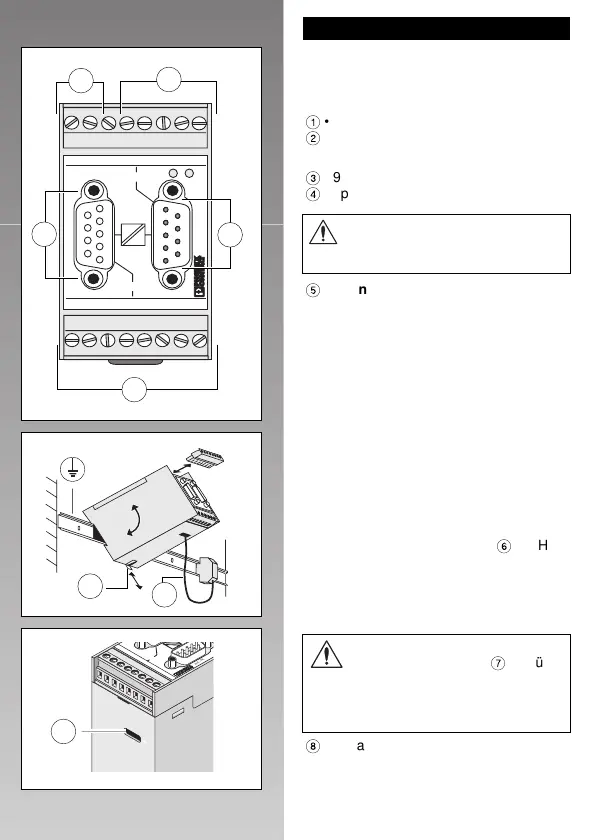
2.1. Anschlüsse (Abb. 3)
RS-232-Schnittstelle:
1
• 9poliger SUB-D(Stift)- oder alternativ
2
• 8poliger COMBICON-Steckverbinder
TTY-Schnittstelle:
3
• 9pol. SUB-D(Buchse)- oder alternativ
4
• 8poliger COMBICON-Steckverbinder
5
Spannungsversorgung des Moduls:
• 24 V DC ± 20 % über den COMBICON-
Steckverbinder (Pin 1 und 2).
2.2. Montage im Schaltschrank (Abb. 4)
Montage (auf 35 mm-Tragschienen
nach DIN EN 50 022) :
Hängen Sie das Gerät in die Oberkante der
Tragschiene und rasten Sie es nach unten
ein.
Demontage:
Ziehen Sie den Schnappriegel
6
mit Hilfe
eines Schraubendrehers zurück und hän-
gen Sie das Gerät nach oben aus.
2.3. Erdanschluß (Abb. 4/5)
8
Zentraler Erdanschluß am Modul:
• separate Schraubklemme auf der Ge-
häuseunterseite (empfohlene Leiter-
querschnitte: 1,5 mm
2
bis 2,5 mm
2
)
Abb. 4
12345
6789
24V 0V NC TxD
RxD CTS RTS GND
RS232
12345
6789
T+ T– R+ R–
S1+ S1- S2+ S2-
TTY
PSM-EG-RS232/TTY-P/2K
Art. -Nr. 27 61 25 3
RS232
TTY
RS232
TTY
Abb.3
DEUTSCH
4
Das Vorhandensein der Funktions-
erde (Bezugspotential
7
) ist für
die Schirmung und Transienten-
ableitung zwingend erforderlich
(vgl. Funktionsschaltbild).
PE
TTY
TTY
T
+
T
–
R
+
R
–
S
1
+
S
1
- S
2
+
S
2
-
12345
6789
A
rt.-N
r
. 2
7
6
T+ T
– R
+ R–
TTY
S1+ S1– S
2+ S2–
Abb.5
Nutzen Sie an einer Schnittstelle
nicht SUB-D und COMBICON
gleichzeitig!

 Loading...