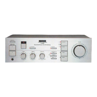
A-607R
22
6. ADJUSTMENTS
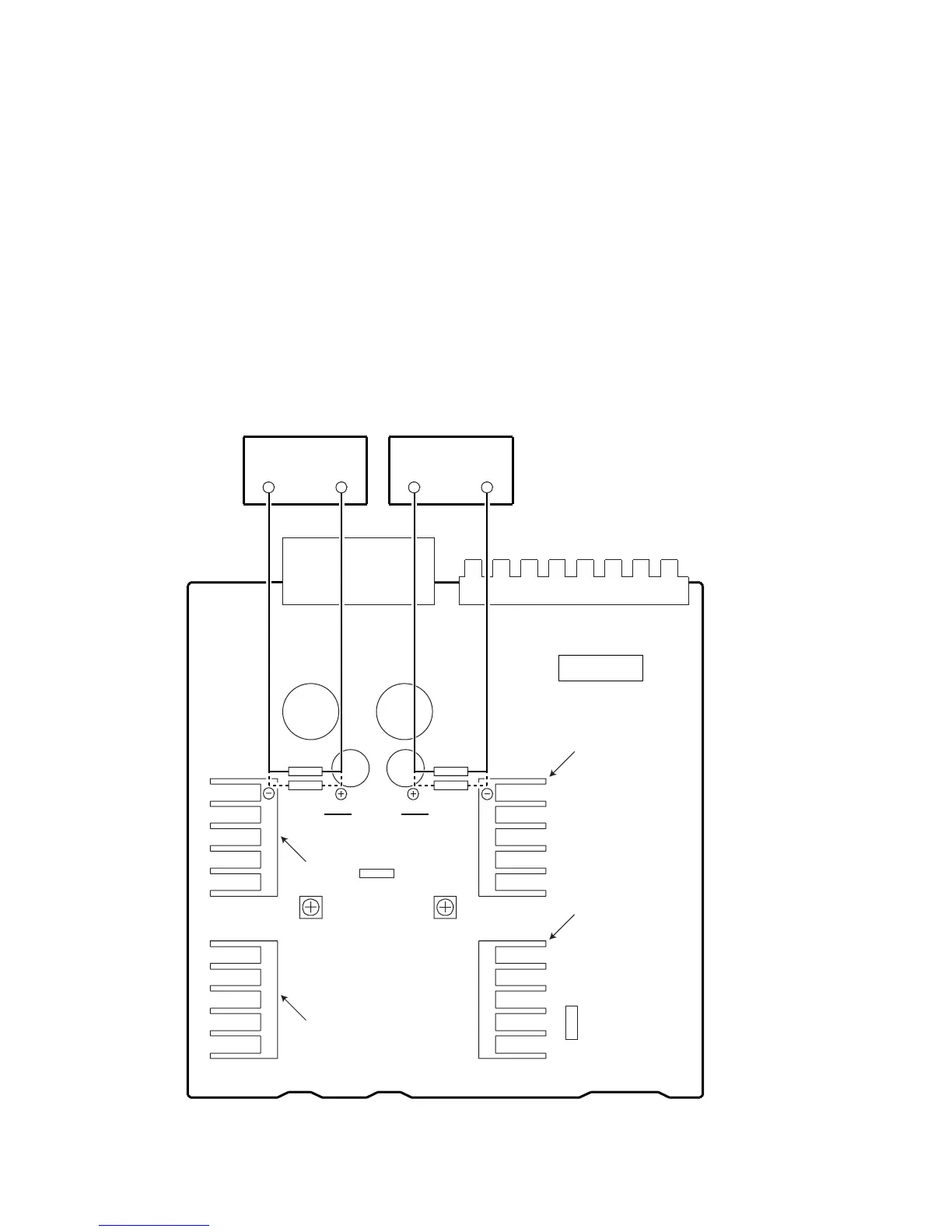
6.1 IDLE CURRENT ADJUSTMENT
¶ CAUTION : Heatsinks’ (Q323–Q326) DC level is equal to +B or -B.
Don’t touch them or you will be electricary chocked.
1. Connect the measuring instrument as Fig.6-1. (R415 or R416)
2. Set the VOLUME CONTROL to minimum, BASS TONE CONTROL to center, TREBLE TONE CONTROL to center and BALANCE CONTROL
to center. Set VR301 and VR302 to minimum.
3. Set the POWER switch to ON.
4. Adjust VR301 (VR302) so that the voltage between both sides of R415 (R416) becomes 16mV±1mV. (Within 10 seconds from when the relay
is turned ON)
5. Ages for 7 minutes.
6. Adjust VR301 (VR302) so that the voltage between both sides of R415 (R416) becomes 11mV±1mV.
VR301 VR302
R413 R414
R415 R416
Heat Sink
CN204
AF ASSY
DC Voltmeter DC Voltmeter
SIDE A
Heat Sink
Heat Sink
Heat Sink
R417
W212
W150
Fig.6-1 Adjustment Method
 Loading...