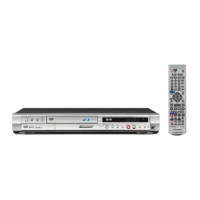
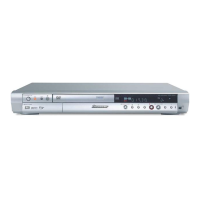
DVR-7000
MAIN ASSY
IC4007 Pin54 (CLKO)
(M65774AFP)
Y output of S terminal
(75Ω termination)
C output of S terminal
(75Ω termination)
No. Adjustment Name
Adj. Point Measurement Point
Adjustment Value
Adjustment State
1
2
27.000000MHZ
± 130Hz
1.00Vp-p ± 40mV
3
4
Master clock free-running adjustment
(Clock system adjustment)
Y level adjustment of CVBS system
(Output system adjustment)
C level adjustment of CVBS system
(Output system adjustment)
Y level adjustment of component system
(Output system adjustment)
PB level adjustment of component system
(Output system adjustment)
PR level adjustment of component system
(Output system adjustment)
VC3001
VR7006
No input signal or during test disc play-
back
Playback the DVD test disc(100%white).
Terminate the Y output of S terminal with
75Ω and adjust so that the level of between
sync tip and white peak becomes 1.0Vp-p.
Playback the DVD test disc(100%white).
At the pin 11 of CN7001 in the MAIN ASSY,
adjust so that the level of between sync tip
and white peak becomes 0.8Vp-p.
Playback the DVD test disc(100%color- bar).
Terminate the C output of S terminal with
75Ω and adjust so that the amplitude of
color burst becomes 286mVp-p.
Playback the DVD test disc(100%color- bar).
At the pin 13 of CN7001 in the MAIN ASSY,
adjust so that the level of between bottom
and top becomes 0.76Vp-p in the 100%
color-bar screen.
Playback the DVD test disc(100%color- bar).
At the pin 15 of CN7001 in the MAIN ASSY,
adjust so that the level of between bottom
and top becomes 0.76Vp-p in the 100%
color-bar screen.
5
VR7003
800mVp-p ± 24mV
286mVp-p ± 11mV
VR7007
VR7004
760mVp-p ± 22mV
6
VR7005
760mVp-p ± 22mV
MAIN ASSY
CN7001 Pin11
(Y Out)
MAIN ASSY
CN7001 Pin13
(P
B Out)
MAIN ASSY
CN7001 Pin15
(P
R Out)
MAIN ASSY
E
SIDE A
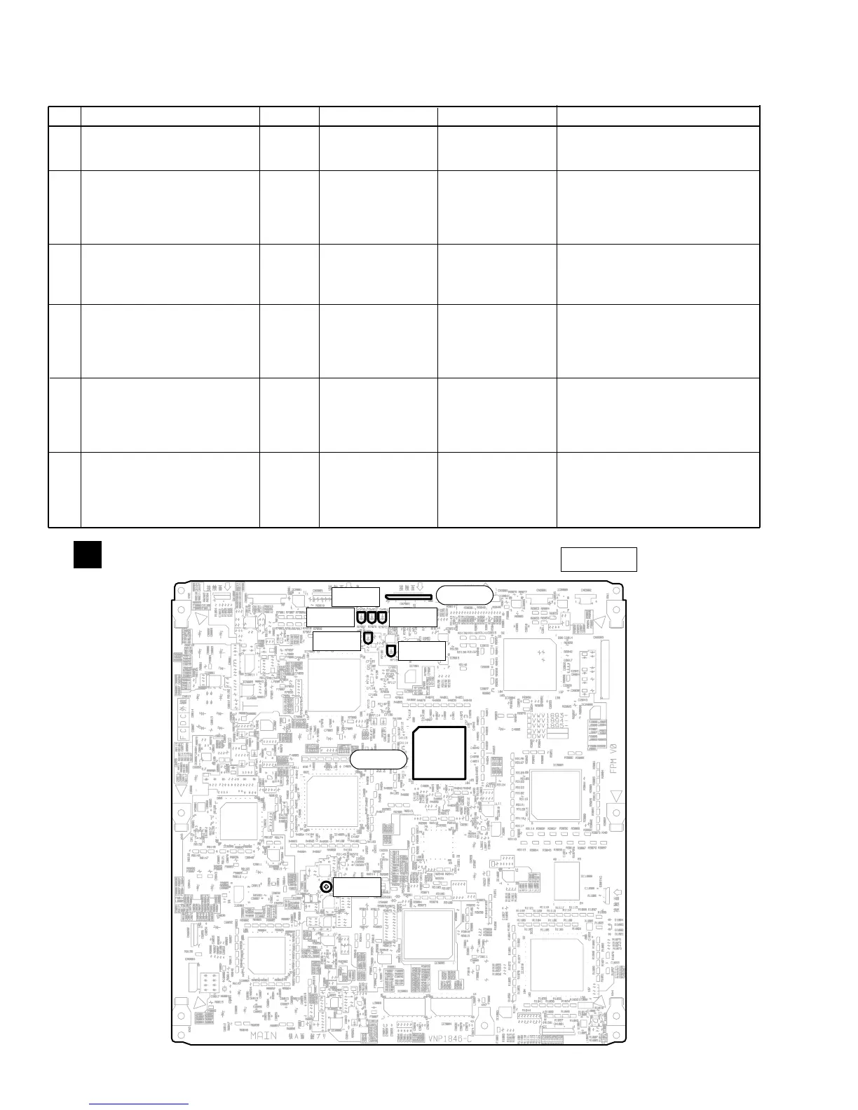
2.3 MAIN ASSY ADJUSTMENT
Note : Use disc : [ DVD test disc GGV1025]
Fig.2 Adjustment Point
VR7005
VR7007
VR7006
VC3001
VR7003
VR7004
CN7001
IC4007
1 22
54
 Loading...