 Loading...
Do you have a question about the Pioneer GM-222 and is the answer not in the manual?
| Channels | 2 |
|---|---|
| Impedance | 4 Ohms |
| Frequency Response | 20 Hz - 20 kHz |
| Signal-to-Noise Ratio | 100 dB |
| THD at Rated Power | 0.08% |
| Crossover Frequency | 80 Hz |
Safety guidelines specifically for the UC model amplifier.
Important warnings and cautions for qualified technicians during repair.
Warning regarding lead in solder and necessary handling precautions.
List of parts associated with the product's packaging.
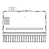
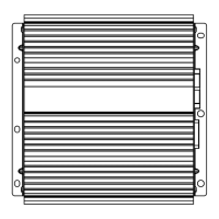
Diagram and identification of external components and their assembly.
Detailed list of external parts with their corresponding part numbers.
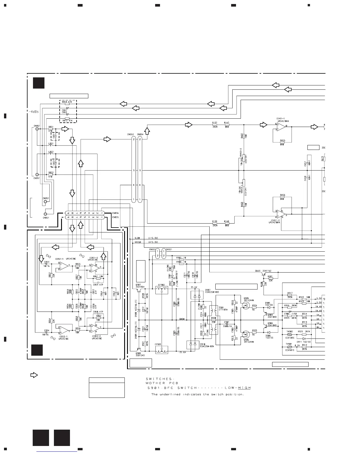
Schematic diagram for the main control board (Mother PCB).
Schematic diagram for the isolator board.
Explanation of audio signal routing within the amplifier.
Connection diagram showing component layout on the Mother PCB.
Connection diagram showing component layout on the Isolator PCB.
Details on chip resistors and chip capacitors used in the unit.
List of miscellaneous electronic components and their part numbers.
List of resistors with their circuit symbols and part numbers.
List of capacitors with their circuit symbols and part numbers.
Notification that no adjustment information is available in this chapter.
Step-by-step instructions for disassembling the unit for servicing.
Procedure for removing the outer case and front panel of the amplifier.
Procedure for detaching the amplifier unit from the heat sink.
Instructions for setting up and operating the amplifier unit.
Explanation of how to adjust the gain control for optimal sound output.
Description of the power indicator light and its function.
Explanation of the BFC switch for controlling beat frequency.
Connection diagram specific to the UC model amplifier.
Connection diagram specific to the ES and EW models amplifier.
Instructions for connecting the blue remote control wire.
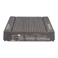
Procedure for connecting the power supply wires to the amplifier.
Guide for connecting speaker wires to the amplifier's output terminals.
Explains different speaker connection modes: stereo, mono, 3-channel.
Details about the required power source voltage and grounding system type.
Specifies current consumption, average draw, and fuse rating.
Physical dimensions and weight of the amplifier unit.
Maximum and continuous power output ratings for different models.
Specifies allowable load impedance and frequency response range.
Signal-to-noise ratio and total harmonic distortion specifications.
Channel separation and input level/impedance requirements.