ELECTRICAL 5 - 6
November 2007 GEM Service Manual
DRIVE AND POWER SYSTEM ERROR CODES
The motor controller monitors the drive system when the vehicle is powered up (key is in the ON position). The
motor controller reports any problems detected by displaying error codes on the multi-purpose LCD display
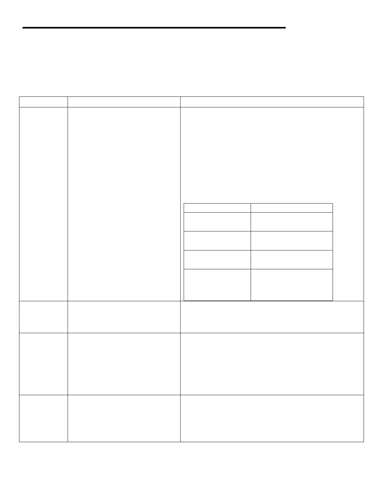
located in the center of the instrument pod. Error codes are explained in the table below. Error codes are
displayed by a service number and on illuminated wrench icon on the LCD display.
Error Code Fault Description Corrective Action
None
Display on the liquid crystal display
(LCD) is blank.
Verify that the following fuses are OK. See fuse chart below.
If OK, check for voltage at Display Connector IPS Harness,
D2 pin A. If no voltage is present, repair the circuit. Refer to
Display Circuit Diagram.
Make sure the key switch is closed. If the switch is closed,
verify voltage is present between the motor controller
connector, CH1 harness, pin 2 and the controller negative
terminal. Refer to the Main Contactor Circuit Diagram.
Check for an open circuit or loose connection from the “Y”
plug and the LCD. If voltage is present, and there are no
loose connections, replace the LCD.
Fuse Position Symptom
Fuse F5
• No display
• Vehicle Moves
Fuse F9
• No display
• No Movement
Fuse F13
• No display
• No Movement
Fuse in DC/DC
Converter – NOTE:
Not available in
2007 models.
• No display
• No Movement
05 Start switch failed to close. Check start switch circuit from motor controller to start
switch. Start switch may be defective. Refer to the Motor
Controller Circuit Diagram for troubleshooting the start
switch circuit.
06
Accelerator pedal was pushed and
there is improper or no contact at
the drive mode switch (defective
switch as indicated by a short inside
or not in the correct position -
between the positions).
Release the accelerator pedal, make sure the drive mode
switch is in the correct position and then push the
accelerator pedal. If the problem persists, turn the key
switch off, turn the master disconnect switch to off and use
the Motor Controller Circuit Diagram for troubleshooting the
wiring between the PSDM, drive mode switch and the motor
controller. See Troubleshooting Diagram A.
08 Accelerator voltage input is too high
on power up after initial key switch
closure.
Refer to the Motor Controller Circuit Diagram for
troubleshooting the drive mode switch circuit. The
accelerator pedal input to the motor controller, CH1 harness,
pin 7, should be less than 0.9 VDC before pressing the
pedal. If the voltage is greater than 0.9 VDC, the accelerator
pedal may be defective.
 Loading...