EasyManua.ls Logo

Proceq Pprofometer 600 User Manual

Proceq Pprofometer 600
53 pages
To Next Page IconTo Next Page
To Previous Page IconTo Previous Page
Page #9 background image
9 © 2017 Proceq SA
3. Profometer 6 Cover Meter
3.1 Measuring Principle
3.1.1. Pulse induction
The Profometer 6 uses electromagnetic pulse induction technology to
detect rebars. Coils in the probe are periodically charged by current
pulses and thus generate a magnetic field. On the surface of any electri-
cally conductive material which is in the magnetic field, eddy currents are
produced. They induce a magnetic field in the opposite direction. The
resulting change in voltage can be utilized for the measurement.
Coils
Concrete
Rebar
Magnetic Field
Figure 2: Measurement principle
The Profometer 6 uses different coil arrangements to generate several
magnetic fields. Advanced signal processing allows locating a rebar as
well as measuring of cover and rebar diameter.
This method is unaffected by all non conductive materials such as con-
crete, wood, plastics, bricks etc. However any kind of conductive materi-
als within the magnetic field (sphere of approx. 200 mm / 8 inch radius)
will have an influence on the measurement.
NOTE! Remove all metallic objects such as rings and watch-
es before you start measuring.
3.1.2. Calibrated Measuring with Profometer 6
The Profometer 6 is calibrated to measure on a normal rebar arrange-
ment; which is an arrangement of non-stainless steel rebars fastened
with binding wires only e. g. when measuring on welded mesh wires the
cover and diameter readings must be corrected (see “3.2.4. Practical
Hints”). The following information on accuracy, measuring ranges and
resolutions refer to measurements on normal rebar arrangements.
3.1.3. The
Measuring
Range
The measuring range is dependent on the bar size. The expected ac-
curacy of the cover measurement is indicated in the graphic below. It
complies with BS1881 part 204, for a single rebar with sufficient spacing.
0
10
20
30
40
50
60
70
80
90
100
110
120
130
140
150
160
170
180
190
5 10 15 20 25 30 35 40 45 50 55
7
6
5
4
3
2
1
#2 #3 #5
#6 #8 #9
#11 #13 #14 #16 #18
[inch] [mm]
Rebar size
Cover depth
Spot probe
measuring range
Standard
measuring range
±4 mm
±2 mm
±1 mm
±1 mm
[mm]
[
1
/
8
inch]
153 mm
50 mm
Large
measuring range
measuring
accuray
185 mm
100 mm
Figure 3: Measuring ranges and accuracy: up to the indicated limits the
cover is measured and displayed. In the Locating Mode a rebar
is shown. In the Single-Line Mode the cover curve is shown but
a rebar is only set up to 90 % of the maximum cover.
Question and Answer IconNeed help?

Do you have a question about the Proceq Pprofometer 600 and is the answer not in the manual?

Proceq Pprofometer 600 Specifications

General IconGeneral
Operating Temperature-10°C to +50°C
Storage Temperature-20°C to +60°C
Battery LifeUp to 8 hours
IP RatingIP54
Cover measurement rangeUp to 185 mm
Bar diameter measurement range6 mm to 50 mm
Accuracy of cover measurement±1 to 4 mm depending on cover depth
DisplayColor touchscreen
Data storageInternal memory
Data transferUSB
Power supplyRechargeable Li-ion battery
Accuracy±1 mm to ±5 mm (cover)
ConnectivityUSB

Summary

Safety and Liability

General Information, Liability, and Safety

Covers manual purpose, liability terms, and general safety warnings.

Correct Usage Guidelines

Details the proper and intended use of the instrument.

General Operation

Getting Started and Battery Installation

Guides on initial setup, battery installation, and energy saving.

Main Menu, Upgrades, and Functionalities

Explains the main menu, upgrade procedures, and feature access.

Profometer 6 Cover Meter

Measuring Principle and Calibration

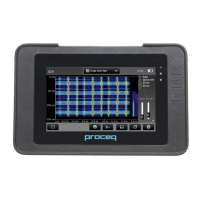
Explains pulse induction technology, calibration, and accuracy.

Resolution, Range, and Sphere of Influence

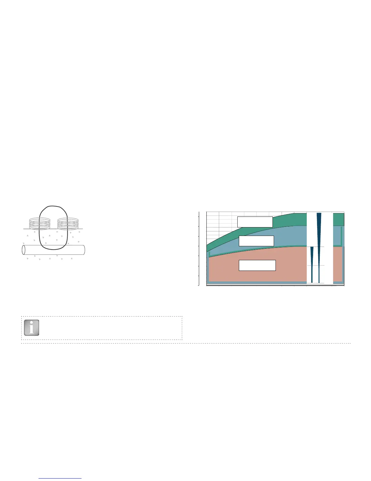
Details measurement ranges, resolution, and material influence.

Cover Meter Operation and Modes

Describes operation, settings, and various measurement modes.

Profometer Corrosion

Measuring Principle and Factors Affecting Measurement

Explains half-cell potential measurement and influencing factors.

Corrosion Operation and Settings

Guides on electrode preparation, grid setup, and corrosion settings.

Corrosion Modes and Display Views

Details modes like Corrosion-Scan and display views like Distribution.

Explorer Document Handling

File Management and Data Transfer

Guides on managing saved files and transferring data via USB.

Ordering Information

Units, Upgrades, and Accessories

Lists product units, upgrade kits, and available parts/accessories.

Technical Specifications

Profometer 6 Cover Meter and Corrosion Specs

Provides detailed technical specifications for both device modes.

Maintenance and Support

Instrument and Electrode Maintenance

Details cleaning procedures for the instrument and electrodes.

Support, Warranty, and Disposal

Information on support services, warranty, and product disposal.

Profometer Link Software

Software Installation and Connection

Guides on starting, installing, and connecting the Profometer Link software.

Viewing and Exporting Measurement Data

Explains how to view, edit, move, and export measurement data.

Merging Scans and Further Functions

Details merging corrosion scans and other software functionalities.

Appendices

Rebar Diameters, Spacing, and Cover References

Provides reference tables for rebar diameters, spacing, and cover.

Related product manuals