810-1902-03 Rev D TM1 Installation Guide
11
Wiring Terminations
The following section outlines the wiring terminations for power, I/O, and relays
Power
Input: 100 to 240VAC, 50/60Hz
Power: 120VAC - Max 0.5A, nominal 0.1A @ 25°C
240VAC – Max 0.25A, nominal 0.05A @ 25C
NOTE: A switch or circuit breaker should be installed in close proximity to the equipment, easily
accessible by an operator and be clearly marked as identifying its use. The equipment is to be
installed in accordance with local and national electrical codes and installed by a licensed electrical
installer. Remove the 4 thumb-screws (or socket-head screws) securing the cover of the TM1.
1. Determine the power source for the TM1 (e.g. 120VAC, 240VAC.). Make sure the power
is locked out at the source.
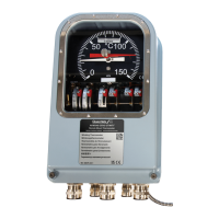
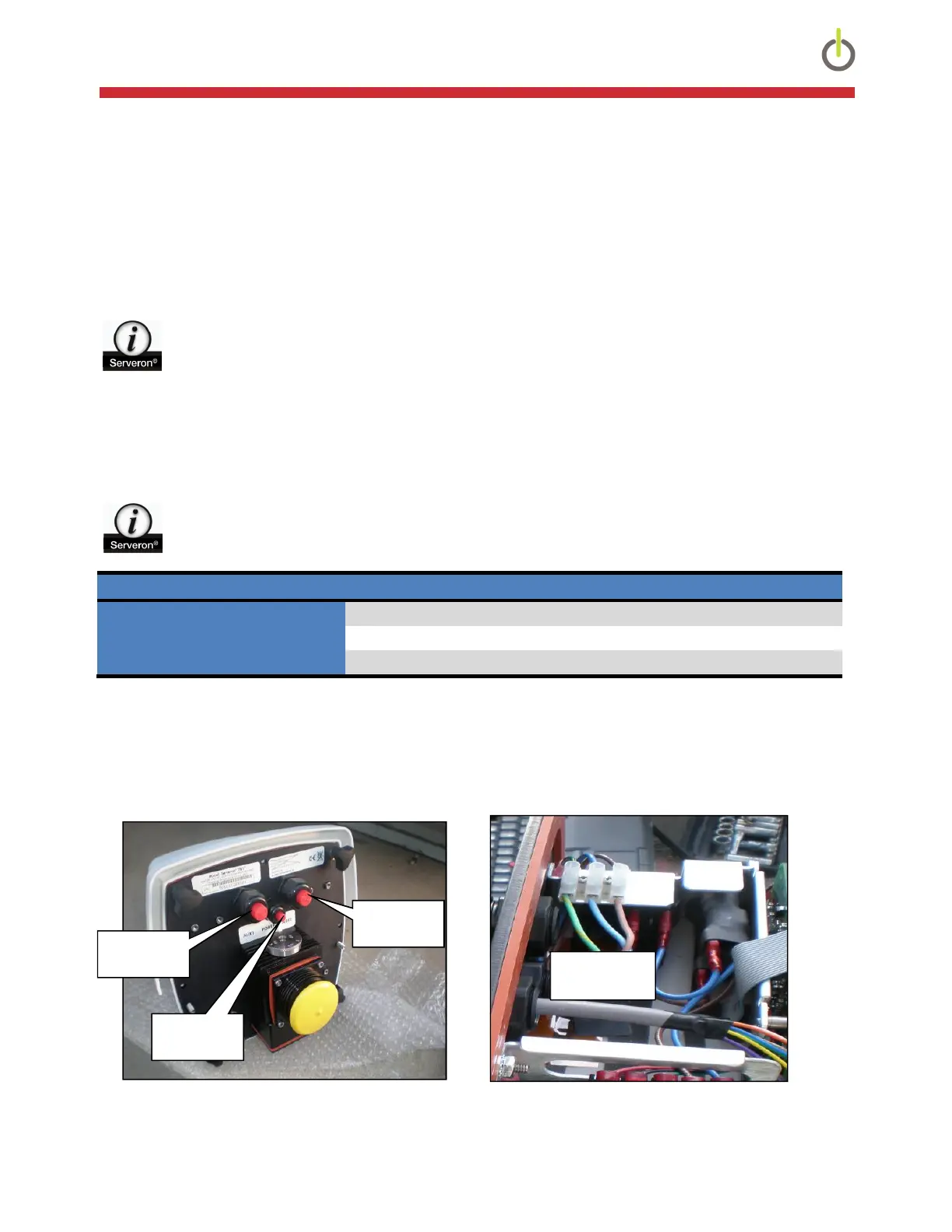
2. Insert the power cable through the small center gland fitting and connect as follows:
NOTE: Recommended minimum torque for the power connector terminal is 5 in-lbs.
Terminal Conmnections 120VAc 240VAC
Earth GND GRN/YLW GRN/YLW
L1 BRN or BLK - Line RED
L2 BLUE or WHT - Neutral BLK
Table 3: Power Terminations
3. Tighten the gland fitting to provide a secure weather-tight seal.
4. Source power should remain off until all wiring service has been completed.
Figure 10: Cable Locations Figure 11: Power Terminals
AUX2
GND, L2, L1
AUX1
Power
 Loading...