810-1902-03 Rev D TM1 Installation Guide
14
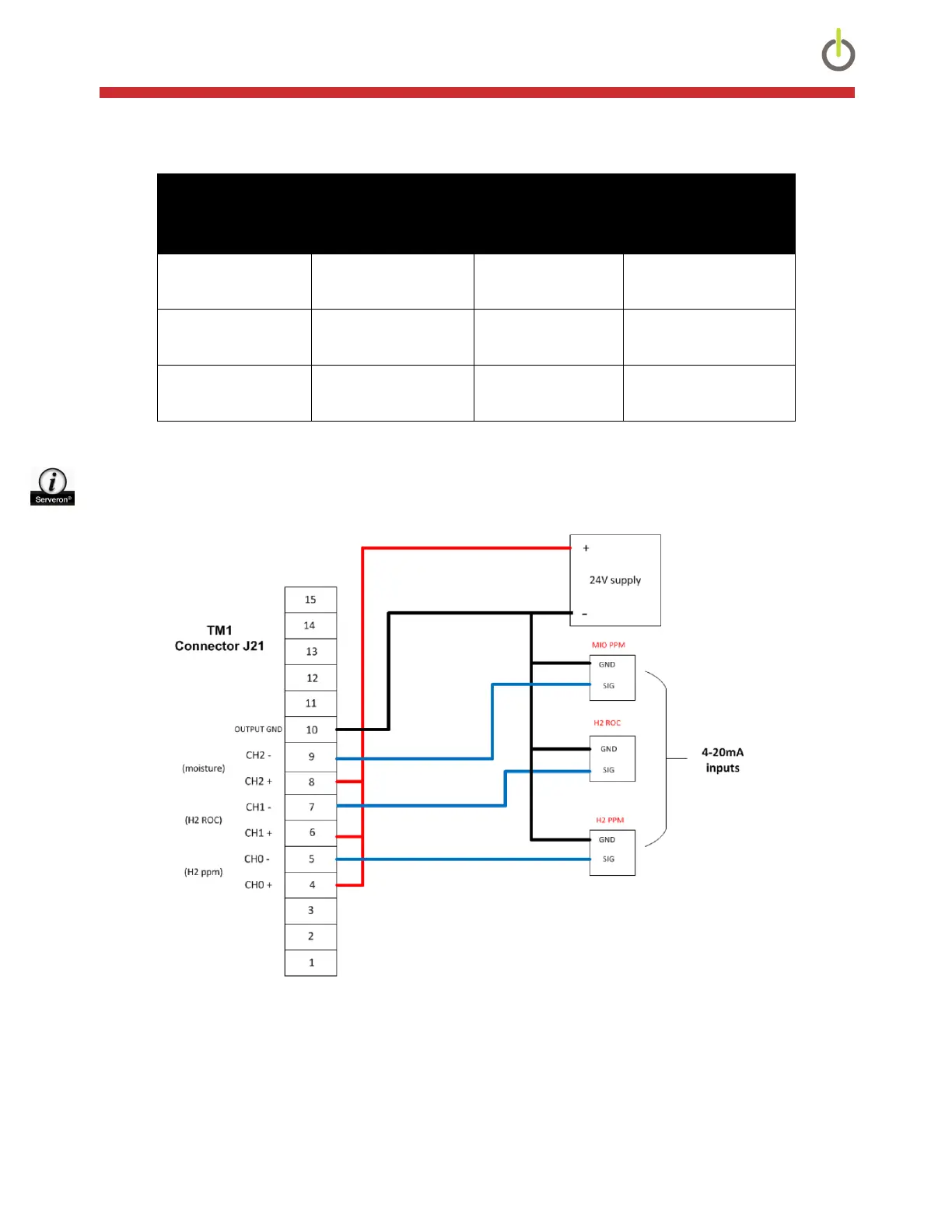
4-20mA Output Wiring
4-20 Output AUX Channel Cover Label
Reference
Config Manual
Reference
H2 PPM 3 CH0 CH1
H2 ROC 4 CH1 CH2
Moisture PPM 5 CH2 CH3
Table 4: 4-20mA Outputs
NOTE: The 4-20mA outputs require a 24VDC power source for their operation, which is not supplied
by the TM1, unless the optional 24V 4-20mA Output PS Module (900-0184-00) is purchased.
Figure 14: 4-20mA Output Wiring
Once the wiring is completed, the 4-20mA outputs must be configured in the TM1 monitor, using the TM1
Configuration Utility, which is included on the supplied USB flash drive. For instructions on the use of the Utility,
refer to the TM1 Configuration Utility User Manual in the Help menu within the software.
 Loading...