GL300W External Battery Kit User Manual
GL300WEBKUM001 -11-
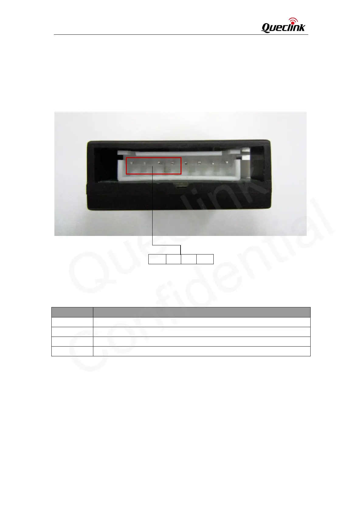
3.2.2. Digital Input Interface
Digital Input interface includes 2 digital inputs which can be used to monitor the external digital
signal. They can be connected to toggle switch, tact switch or reed switch. There are four pins on
the left side of the 8-pin connector. The pin description is shown in Table 5.
Figure 4: Digital Input Interface
Table 5: Digital Input Interface Reference
Pin Number Description
1 Digital input 1
2 Digital input 2
3 2.8V output
4 GND
3.2.2.1. Digital Input 1
Digital input 1 work as a lock switch and it is recommended to connect to a toggle switch or a
reed switch.
If SW103 is set to ‘H’, the logical status is ‘0’ when the electrical level of digital input 1 is high. It
will be ‘1’ if the electrical level of digital input 1 is low.
If SW103 is set to ‘L’, the logical status is ‘1’ when the electrical level of digital input 1 is high. It
will be ‘0’ if the electrical level of digital input 1 is low.
1 2 3 4
 Loading...