GL300W External Battery Kit User Manual
GL300WEBKUM001 -14-
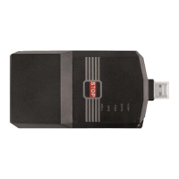
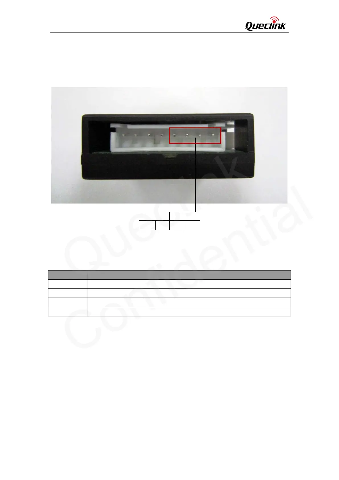
3.2.3. PWR Output Interface
The power output is included in the PWR Output interface. It also includes the UART interface for
the communication between GL300W and PCU. There are four pins on the right side of the 8-pin
connector. The pin description is shown in Table 6.
Figure 9: PWR Output Interface
Table 6: PWR Output Interface Reference
Pin Number Description
5 RXD
6 TXD
7 GND
8
Power output(3.4V~4.2V)
3.3. Toggle Switch
The PCU has four toggle switches: SW101 to SW104. They are used for the configuration of the
PCU.
5 6 7 8
 Loading...