EN
BTR185 INSTALLATION AND USE MANUAL - REV009A
42
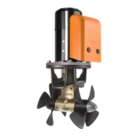
BTR185Thruster’s closing problems
WARNING: disconnect the
BTR propeller from power.
ACTUATOR
STICKER
SLOTTED SCREW
In emergency, the propeller can be locked in the closed position
On the actuator, under the sticker,
there is a slotted screw;
turn it clockwise with a screwdriver
to close the system.
Maintenance BTR185
Quick
®
Thrusters are made in materials that are resistant to the sea environment: In any case, it is indispensable to periodi-
cally remove salt deposits that form on the outer surfaces to avoid corrosions and consequent system inefciency.
WARNING: make sure that the power supply to the electric motor is not switched on when maintenance operations
are carried out.
NR. DESCRIPTION
1 SCREW
2 GROWER
3 MOTOR
4 REVERSING CONTACTOR UNIT
5 WASHER
6 SCREW
7 CARTER REVERSING
CONTACTOR
8 FASTENERS CARTER
REVERSING
CONTACTOR
9 SCREW
10 SCREW
11 FLANGE
12 CHASSIS
13 SCREW
14 WASHER
15 NUT
16 GASKET O-RING
17 O-RING
18 OIL SEAL
19 KEY
20 ACTUATOR’S LEVER
21 ACTUATOR’S PLATE
22 CABLE OUTLET
23 SCREW
24 RRC RX BOX
25 PIN
26 SPRING RING
27 ACTUATOR
28 SCREW
29 FULCRUM
30 PIN
31 ANGLE BAR
32 HINGE’S BRACKET
33 HINGE’S SHAFT
34 SCREW
35 WASHER
36 HINGE’S ARM
37 LID’S BRACKET
38 OIL SEAL
39 INTERNAL CIRCLIP
40 BEARING
41 SHAFT
42 KEY
43 EXTERNAL CIRCLIP
44A BEARING
45 SHAFT SUPPORT
46 OIL SEAL
47 EXTERNAL CIRCLIP
48 PLATE
49 DOUBLE JOINT
50 EXTERNAL CIRCLIP
51 OIL SEAL
52 NUT
53 PIN
54 PIN
55 FULCRUM
56 SCREW
57 ANODE
58 SCREW
59 CABLE-STOPPER
60 SCREW
61 NUT
62 TILTING BODY
63 PIN
64 NUT
65 LEVER
66 LEVER
67 EXTERNAL CIRCLIP
68 SCREW
69 SPRING
70 SHAFT
71 SCREW
72 GROWER
73 O-RING
74 GASKET
75 KEY
76 GEARLEG
77 PLUG
78 PROPELLER 185 R
79 PROPELLER 185 L
80 NUT
81 ANODE
82 SCREW
83 TUNNEL
84 CABLE GUIDE
85 WASHER
86 SCREW
87 SELF-LOCKING NUT
88 WASHER
89 SELF-LOCKING NUT
90 CABLE
Drawing number page 43
49
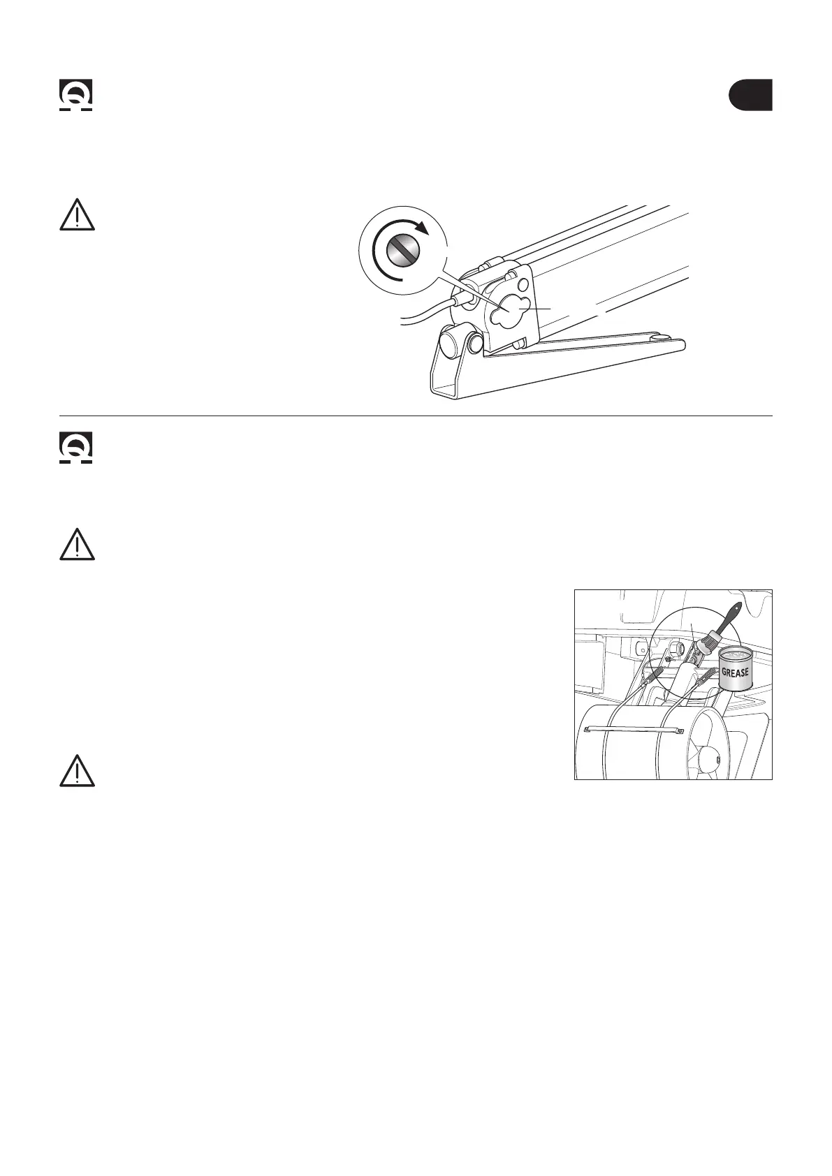
Fig. 25
Dismantle once a year, following the points below:
• Clean propellers (78 and 79), tunnel (83) and gearleg (76).
• Replace the anodes (carry out this operation more often if needed) and,
if possible, grease the double joint (49) with marine grease (g. 25).
• Replace the propellers if damaged or worn out.
• Check the tightness of all screws.
• Ensure that there is no water seepage inside.
• Check that all electrical connections are well tightened and oxide-less.
• Check that the batteries are in good conditions.
WARNING: do not paint the zinc anodes (57 and 81),
the sealings and the gearlegs’ shafts where the propellers are lodged.
 Loading...