EasyManua.ls Logo

Quicksilver 88688A23 User Manual

Quicksilver 88688A23
14 pages
To Next Page IconTo Next Page
To Previous Page IconTo Previous Page
Page #9 background image
3.
Feed control cables, neutral start safety switch wir-
ing harnesses and trim harness thru control base
and opening in mounting panel (cut previously) and
set control in position.
AWARNING
Trim wiring harness must be positioned with plastic
sleeves (on harness) at the exact location shown to
keep harnesses from being pinched or cut by mounting
brackets.
4.
5.
6.
Position trim harness so that plastic sleeve is at the
exact location shown.
Insert mounting screws (4) thru control mounting
brackets, control base and mounting panel. Tighten
securely.
Move one control handle to full Forwardposition
and one control handle to full Reverseposition.
Apply a slight amount of downward force on each
handle to align the 2 control modules, then torque
locknuts (which secure mounting brackets on con-
trol modules together) to 35 Ibs. in.
(4
N.m.)
50058
a
-
Control Base
b
-
Control Mounting Screws
c
-
Locknuts (Torque to 35 lb. in.)
d
-
Plastic Sleeve
AWARNING
Set screws in control handles must be torqued to speci-
fication. Failure to tighten set screws securely could
allow control handles to disengage, with subsequent
loss of throttle and shift control.
7.
Move control handles to allow access to set screws.
Torque set screws to 60 Ibs. in. (7 N.m.)
50058
a
-
Detent Adjustment Screw
b
-
Control Handle Friction Screw
c
-
Set Screw
d
-
Throttle-OnlyButton
8. Install cover by snapping into control base.
Question and Answer IconNeed help?

Do you have a question about the Quicksilver 88688A23 and is the answer not in the manual?

Quicksilver 88688A23 Specifications

General IconGeneral
BrandQuicksilver
Model88688A23
CategoryRemote Control
LanguageEnglish

Summary

Notice and Safety Information

Safety Alerts and Precautions

Information on DANGER, WARNING, and CAUTION symbols for user safety.

Maintenance and Cable Selection

Maintenance and Replacement Parts

Defines service intervals and details checks for fasteners, connections, and lubrication.

Selecting Remote Control Cables

Guidance on choosing correct cable length and ensuring proper fastener torque.

Installation Procedure

Introduction to Dual Handle Trim Control

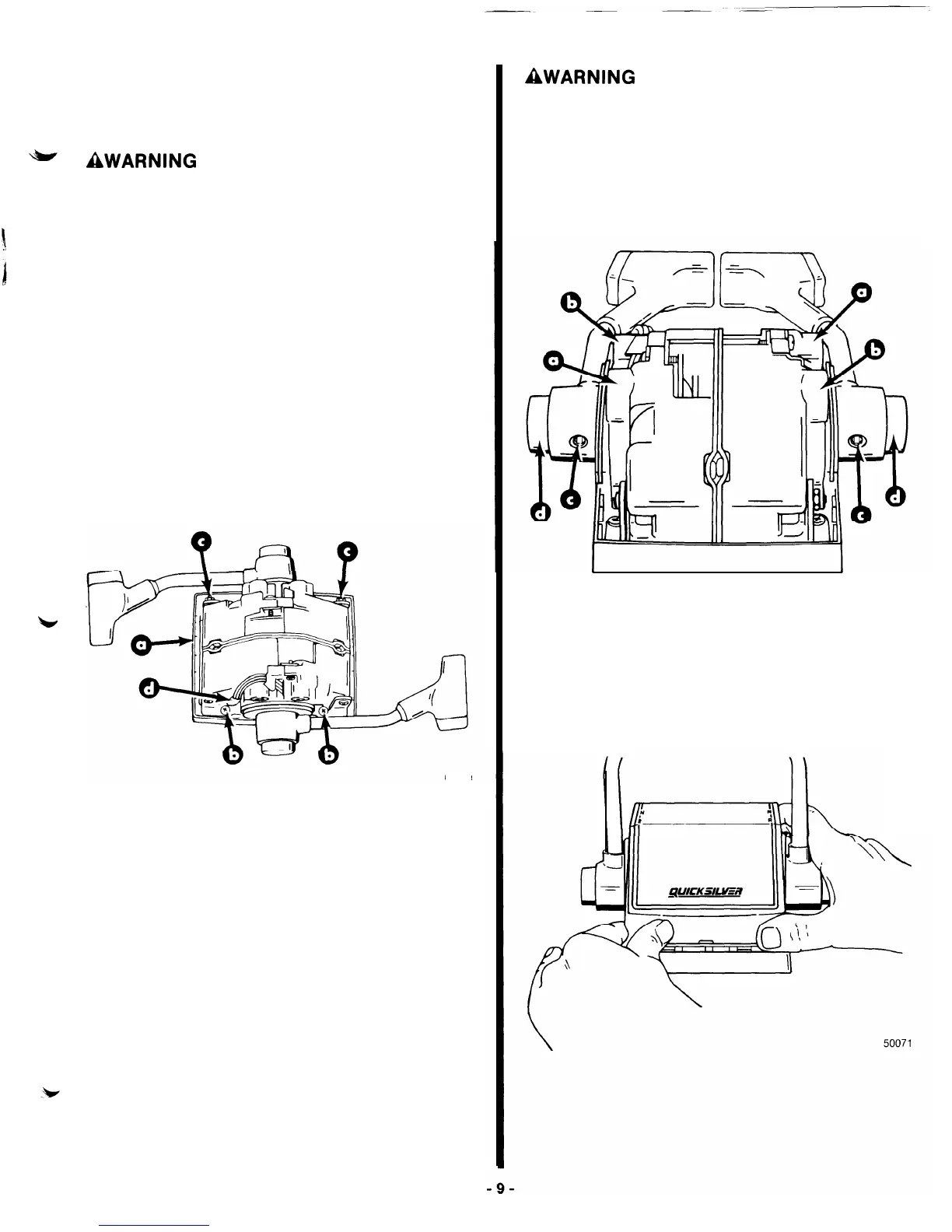
Explains the one-hand operation and features of the console mount control.

Initial Installation Steps

Covers positioning, cable routing, mounting, and wiring connections for the control.

Final Checks and Adjustments

Details checking set screws, handle friction, detent adjustment, and neutral start switch.

Control Cable Routing Best Practices

Ensures proper cable routing to prevent binding and hard shifting.

Cable Installation Details

Starboard Side Cable Install (MerCruiser/Outboard)

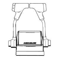
Guides installing shift and throttle cables to the starboard control module.

Port Side Cable Install (MerCruiser/Outboard)

Guides installing shift and throttle cables to the port control module.

Starboard Side Cable Install (Outboard 250 HP 3.4L+)

Installs shift and throttle cables on starboard module for higher HP outboards.

Port Side Cable Install (Outboard 250 HP 3.4L+)

Installs shift and throttle cables on port module for higher HP outboards.

Mounting and Wiring

Remote Control Mounting

Details on selecting, drilling, and securing the mounting location for the control unit.

Trailer Switch Installation

Steps for installing the trailer switch, including hole preparation and securing.

Neutral Safety Switch and Power Trim Connections

Ensures correct wiring of safety switches and trim harnesses for proper function.

Handle Adjustment and Operation

Repositioning Control Handles

Procedure to disconnect, remove, reposition, and reinstall control handles on shafts.

Handle Adjustments and Final Steps

Covers torquing set screws, installing buttons, and reconnecting wiring.

Control Handle Operation

Explains full gear shift, throttle control, throttle-only button, detent, and friction adjustments.

Trim and Trailer Switch Operation

Details on using the trim switch and trailer switch for power package adjustment.