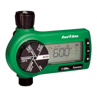
3
24VAC
AC C ES SORY
SENS
12345678CM
RESET
TERMINAL
BLOCK
DIRECT
BURIAL
CABLE
WIRES TO
ZONES 3 & 4
POWER
POWER
COMMON
WIRE
WATER-TIGHT
CONNECTORS
ZONE 1
VALVE
ZONE 2
VALVE
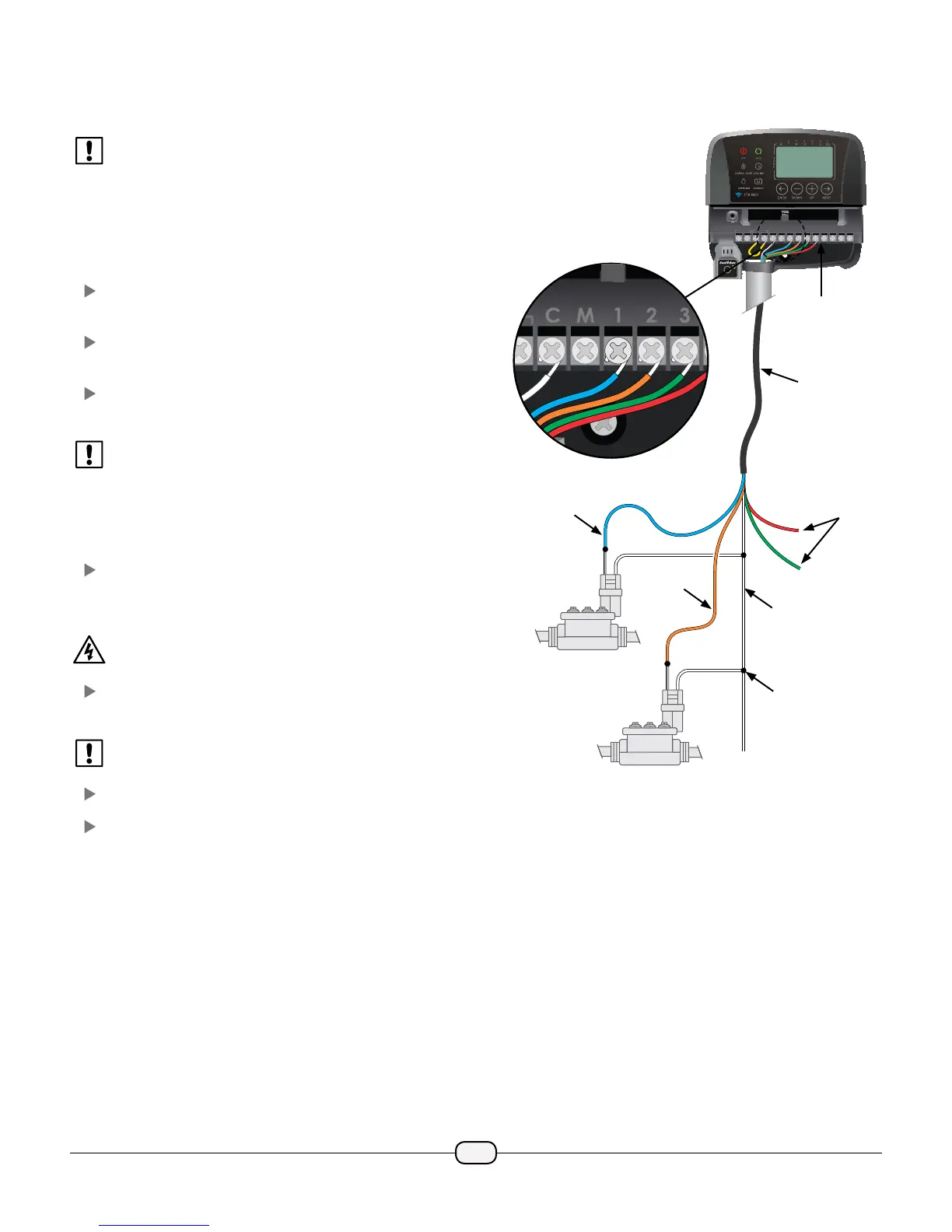
Wiring Connections
Connect the valve wires for each Zone.
NOTE: If installing an outdoor model, route all valve
wires through conduit and through the knock-out
on bottom of the unit.
Connect Zone Valves
Valve Connections
Use direct burial cable to run wiring from the Timer
to valves in the eld.
Connect a color coded wire from the direct burial
cable to either wire on the valve.
Connect the remaining wire on each valve to a
“common” wire which then connects to the Timer.
NOTE: Use water-tight connectors for all wire splice
connections. Depending on your landscape setup,
you may need to run extension wires for the power
and common connections.
Timer Connections
Connect the color coded power wire from each
external valve (or zone) to the corresponding zone
number on the terminal block.
WARNING: To prevent damage to the Timer, connect
only ONE valve to each open terminal.
Connect the common wire to the common (C)
terminal.
NOTE: Do not remove the yellow jumper wire on the
terminals marked SENS.
Check that all wiring connections are secure.
Turn on external power (outdoor model) or plug in
transformer (indoor model).
 Loading...